 |
|||
|
|
|||
|
|
|||
| ||||||||||
|
|
 TM 9-2320-312-24-2
Testing and Adjusting Section
Electrical System
i01665449
Battery - Test
SMCS Code: 1401-081
Most of the tests of the electrical system can be
done on the engine. The wiring insulation must be
in good condition. The wire and cable connections
must be clean, and both components must be tight.
Never disconnect any charging unit circuit or bat-
tery circuit cable from the battery when the charg-
ing unit is operated. A spark can cause an explo-
sion from the flammable vapor mixture of hydro-
gen and oxygen that is released from the elec-
g00283565
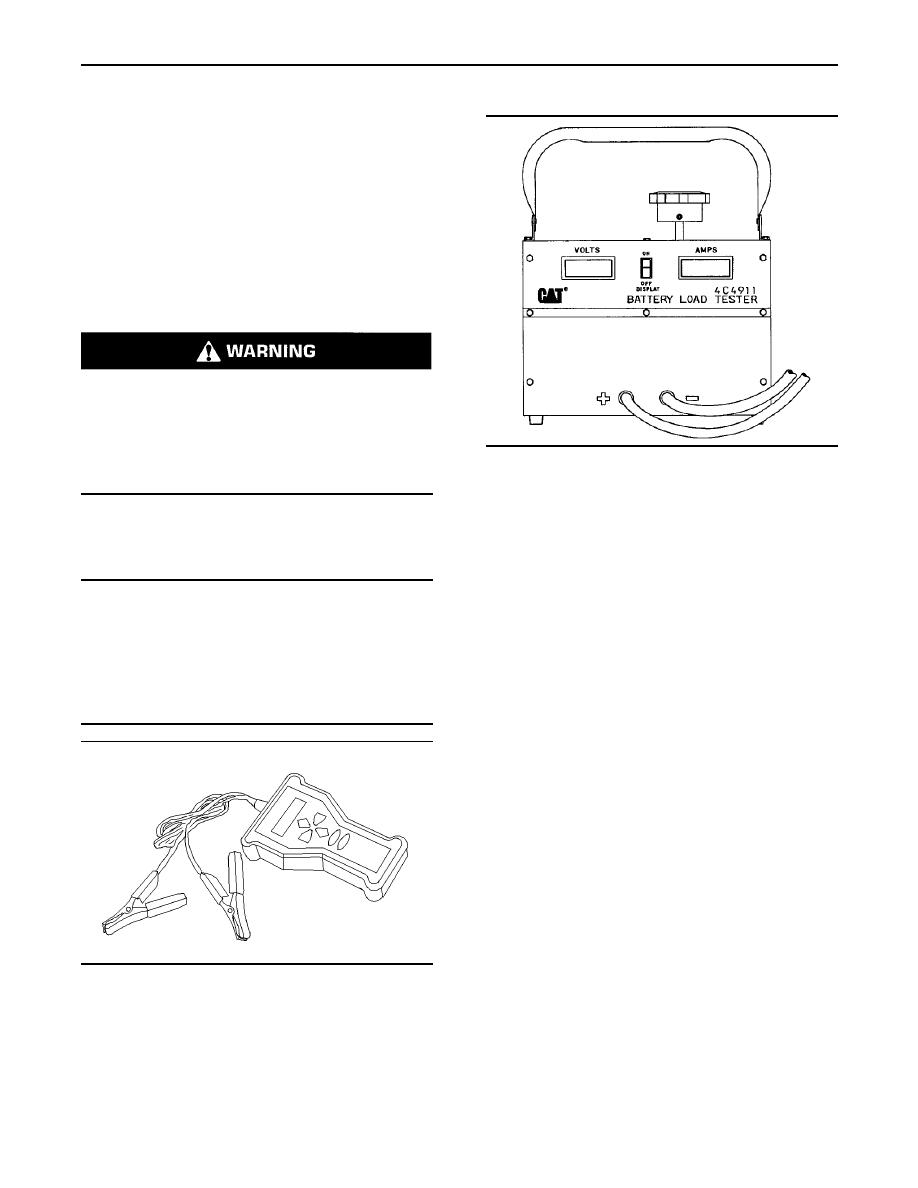
Illustration 90
trolyte through the battery outlets. Injury to per-
sonnel can be the result.
4C-4911 Battery Load Tester
Use the 4C-4911 Battery Load Tester or the
The battery circuit is an electrical load on the
177-2330 Battery Analyzer in order to test a battery
charging unit. The load is variable because of the
that does not maintain a charge when the battery
condition of the charge in the battery.
is active. The 4C-4911 Battery Load Tester or the
177-2330 Battery Analyzer is a portable unit. The
NOTICE
4C-4911 Battery Load Tester or the 177-2330
The charging unit will be damaged if the connections
Battery Analyzer can be used under field conditions
between the battery and the charging unit are broken
and under high temperatures. The tester can be
while the battery is being charged. Damage occurs
used to load test all 6, 8, and 12 Volt batteries. This
because the load from the battery is lost and because
tester has two heavy-duty load cables that can
there is an increase in charging voltage. High voltage
easily be fastened to the battery terminals. A load
will damage the charging unit, the regulator, and other
adjustment knob is located on the top of the tester.
electrical components.
The load adjustment knob permits the current that
is being drawn from the battery to be adjusted to a
maximum of 1000 amperes. The tester is cooled by
an internal fan that is automatically activated when
a load is applied.
The tester has a built-in LCD. The LCD is a digital
voltmeter. The LCD is a digital meter that will
also display the amperage. The digital voltmeter
accurately measures the battery voltage at the
battery through wires for tracing. These wires are
buried inside the load cables. The digital meter,
that displays the amperage, accurately displays the
current that is being drawn from the battery which
is being tested.
Note: Refer to Operating Manual , SEHS9249 for
g00859857
Illustration 89
detailed instruction on the use of the 4C-4911
177-2330 Battery Analyzer
Battery Load Tester. Refer to Operating Manual ,
NEHS0764 for detailed instruction on the use of the
177-2330 Battery Analyzer. See Special Instruction,
SEHS7633, "Battery Test Procedure" for the correct
procedures to use when you test the battery. This
publication also contains the specifications to use
when you test the battery.
|
|
Privacy Statement - Press Release - Copyright Information. - Contact Us |
