 |
|||
|
|
|||
|
|
|||
| ||||||||||
|
|
 TM 9-2320-312-24-2
Testing and Adjusting Section
i01851185
i01280287
Gear Group (Front) - Time
Unit Injector - Test
SMCS Code: 1206-531
SMCS Code: 1290-081
This procedure assists in identifying the cause for
an injector misfiring. Perform this procedure only
after performing the Cylinder Cutout Test. Refer to
Troubleshooting, "Injector Solenoids Circuits Test"
for more information.
1. Check for air in the fuel, if this procedure has not
already been performed. Refer to Testing and
Adjusting, "Air in Fuel - Test".
Electrical shock hazard. The electronic unit injec-
tor system uses 90-120 volts.
2. Remove the valve cover and look for broken
parts. Repair any broken parts or replace any
broken parts that are found. Inspect all wiring for
the solenoids. Look for loose connections. Also
look for frayed wires or broken wires. Ensure
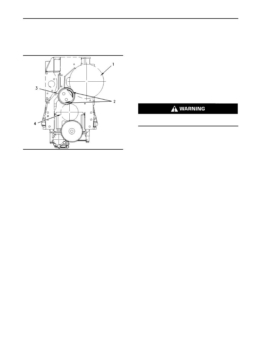
g00943251
Illustration 51
that the connector for the unit injector solenoid
Front gear group
is properly connected. Perform a pull test on
(1) Camshaft gear and timing reference gear
each of the wires.
(2) Timing marks
(3) Idler gear
3. Look for signs of fuel leakage. Investigate the
(4) Crankshaft gear
source of the leaking fuel. Remedy the cause of
Correct fuel injection timing and correct valve
the fuel leak.
mechanism operation is determined by the timing
4. Check the valve lash setting for the cylinder of
reference gear and the alignment of the front gear
group. The timing reference gear is located on the
the suspect unit injector. Refer to Testing and
camshaft gear. The timing reference gear is used
Adjusting, "Engine Valve Lash - Inspect/Adjust".
to measure crankshaft rotation. During installation
of the front gear, timing marks (2) on idler gear
5. Ensure that the bolts that hold the unit injector
(3) must be in alignment with the timing marks
are tightened to the proper torque. In order to
on crankshaft gear (4) and the timing marks on
check the torque, loosen the bolts that hold
camshaft gear (1).
the unit injector. Tighten the bolts to the proper
torque. Refer to either the Disassembly and
Check the teeth on the timing reference gear. The
Assembly Manual , "Unit Injector - Install" or the
teeth should not be defaced. The teeth should have
Specifications Manual , "Unit Injector - Install" for
sharp clean edges and the teeth should be free of
the proper tightening procedure.
Note: The electronic injection timing must be
calibrated after reassembly of the front gear train.
Refer to Troubleshooting, "Engine Speed/Timing
|
|
Privacy Statement - Press Release - Copyright Information. - Contact Us |
