 |
|||
|
|
|||
|
Page Title:
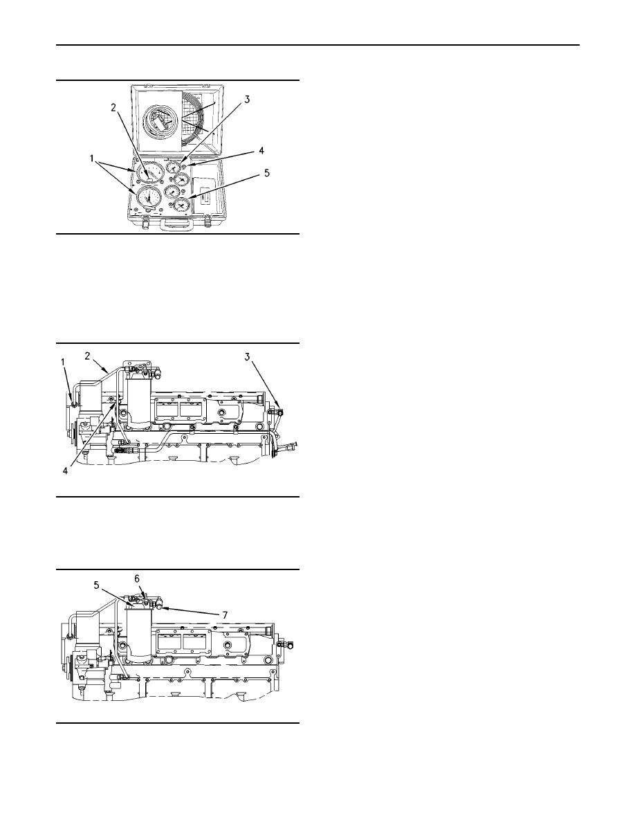
Illustration 48 1U-5470 Engine Pressure Test Group |
|
||
| ||||||||||
|
|
 65
TM 9-2320-312-24-2
Testing and Adjusting Section
During both normal operating conditions and load
conditions, the fuel pressure should register the
following range:
400 to 525 kPa (58 to 76 psi)
At low idle, the fuel pressure at the fuel filter's inlet
should be at the following amount:
400 to 435 kPa (58 to 63 psi)
The fuel pressure to fuel supply passage (1) should
be the same amount, if you subtract the change in
pressure (delta P) across the filter.
g00284796
Illustration 48
With a new filter, the pressure drop across the fuel
filter typically registers the following amount:
1U-5470 Engine Pressure Test Group
(1) Pressure indicators. (2) Zero adjustment screw. (3) Pressure
35 kPa (5 psi)
indicator. (4) Pressure tap. (5) Pressure indicator.
This tool group has a gauge that is used to register
As abrasive particles collect in the fuel filter, the
the pressure in the fuel manifolds. The Special
pressure differential across the filter will increase.
Instruction, SEHS8907 is with the tool group.
When a filter becomes plugged, fuel supply
pressure may drop as low as 69 kPa (10 psi)
before a significant power loss is detected by the
operator. Low fuel pressure will cause cavitation
and internal damage to the unit injectors. The
pressure differential across the fuel filter should
not exceed 69 kPa (10 psi).
Pressure regulator (3) is mounted directly in the
cylinder head. The regulator is located at the fuel
return port toward the rear end of the fuel supply
passage (1). The orifice maintains fuel pressure at
low engine rpm.
To check the unfiltered fuel pressure, follow this
procedure:
g00296502
Illustration 49
1. Remove the plug from fuel pressure tap (6).
Fuel Return Line (Typical Example)
(1) Fuel supply passage. (2) Tube assembly (CPU to fuel supply
2. Install the connector, the seal, and the engine
passage). (3) Pressure regulator. (4) Tube assembly (fuel transfer
pump to fuel filter).
pressure test group to fuel pressure tap (6).
This will obtain the fuel transfer pump pressure.
To check the fuel pressure in the fuel supply
passage (1), follow these steps:
1. Remove the plug from fuel pressure tap (7).
2. Install the adapter, the seal, and the engine
pressure test group to fuel pressure tap (7).
3. Operate the engine.
Note: Make sure that the fuel filter is clean before
you check the fuel pressure. A restricted fuel filter
g00296503
Illustration 50
causes lower fuel pressure at fuel pressure tap (7)
Fuel Pressure Test (Typical Example)
than the fuel pressure at fuel pressure tap (6).
(5) Fuel filter base. (6) Fuel pressure tap (unfiltered tap). (7) Fuel
pressure tap (filtered tap).
|
|
Privacy Statement - Press Release - Copyright Information. - Contact Us |
