 |
|||
|
|
|||
|
|
|||
| ||||||||||
|
|
 TM 9-2320-312-24-2
Testing and Adjusting Section
3. If excessive air is seen in the sight gauge in the
i01287795
fuel return line, install a second sight gauge at
Engine Speed - Check
the inlet to the fuel transfer pump. If a second
sight gauge is not available, move the sight
SMCS Code: 1000
gauge from the fuel return line and install the
sight gauge at the inlet to the fuel transfer pump.
Table 3
Observe the fuel flow during engine cranking.
Look for air bubbles in the fuel. If the engine
Tools Needed
starts, check for air in the fuel at varying engine
Part
Part Name
Quantity
speeds.
Number
1U-6602
1
Photo-Tachometer(1)
If excessive air is not seen at the inlet to the fuel
or
or
transfer pump, the air is entering the system after
9U-7400
Multitach Tool Group
the fuel transfer pump. Proceed to Step 6.
(1)
This unit is a hand-held service tool.
If excessive air is seen at the inlet to the fuel
transfer pump, air is entering through the suction
Note: The Electronic Service Tools can also be used.
side of the fuel system.
You can observe the engine rpm, which is displayed
on the status screen of the electronic service tool.
To avoid personal injury, always wear eye and face
protection when using pressurized air.
NOTICE
To avoid damage, do not use more than 55 kPa (8 psi)
to pressurize the fuel tank.
4. Pressurize the fuel tank to 35 kPa (5 psi). Do not
use more than 55 kPa (8 psi) in order to avoid
damage to the fuel tank. Check for leaks in the
fuel lines between the fuel tank and the fuel
transfer pump. Repair any leaks that are found.
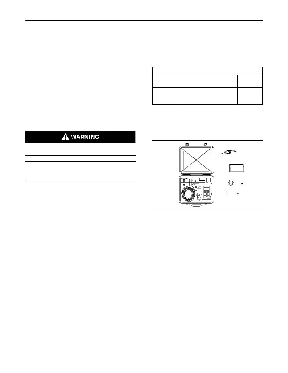
g00286276
Illustration 44
Check the fuel pressure in order to ensure that
the fuel transfer pump is operating properly. For
9U-7400 Multitach Tool Group
information about checking the fuel pressure, see
Testing and Adjusting, "Fuel System Pressure
The 9U-7400 Multitach Tool Group can measure
- Test".
engine rpm from a magnetic pickup. This magnetic
pickup is located in the flywheel housing. The
5. If the source of the air is not found, disconnect
multitach also uses the ability to measure engine
the supply line from the fuel tank and connect an
rpm from visual engine parts that are rotating.
external fuel supply to the inlet of the fuel transfer
pump. If this corrects the problem, repair the fuel
Note: Refer to Special Instruction, NEHS0605 that
tank or the stand pipe in the fuel tank.
is with the 9U-7400 Multitach Tool Group. This
manual gives instructions for the test procedure.
6. If the injector sleeve is worn or damaged,
combustion gases may be leaking into the
The 1U-6602 Photo-Tachometer is a phototach for
fuel system. Also, if the O-rings on the injector
general use. This tachometer can only register the
sleeves are worn, missing, or damaged,
basic input frequency on any rotating part that is
combustion gases may leak into the fuel system.
visible. The basic input frequency is 1 pulse per
revolution per piece of reflective tape.
Note: Refer to Special Instruction, SEHS8854 that is
with this group. This manual provides instructions
for using this tool.
Note: The measurement of engine rpm can be set
with the Electronic Service Tool. Refer to Electronic
Troubleshooting.
|
|
Privacy Statement - Press Release - Copyright Information. - Contact Us |
