 |
|||
|
|
|||
|
|
|||
| ||||||||||
|
|
 TM 9-2320-312-24-1
TRANSMISSION REPLACEMENT - CONTINUED
0139 00
INSTALLATION - CONTINUED
6.
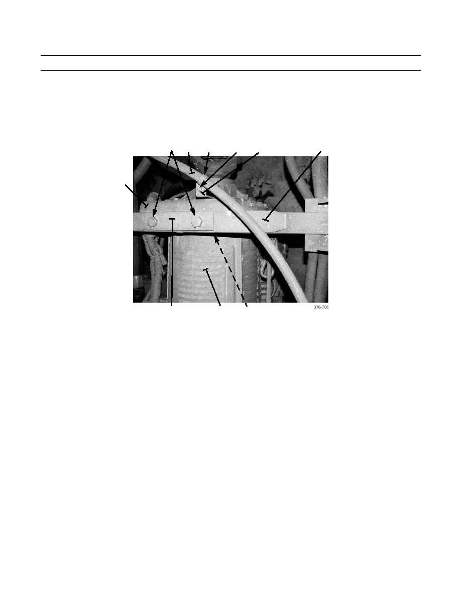
Position spacers (10), tail shaft support spring (9), and spring cap (12) at transmission mounting bracket (1). Install
two bolts (3) and new locknuts (2). Tighten locknuts to 240 lb-ft (325 Nm).
7.
Secure air dryer-to-air compressor hose (4) to standoff bracket (8) with clamps (5), bolt (7), and nut (6).
2,3
4
5
9
6,7
8
1
11
12
10
8.
Tighten 12 bolts (15) to 38 lb-ft (52 Nm).
WARNING
Do not place finger in hole in engine bell housing while engine is being barred over. Failure to follow
this warning could result in injury.
CAUTION
Step 9 must be followed to bar engine over. Any other method may damage engine.
If bolts are dropped in engine bell housing, retrieve immediately by removing four bolts and access
cover at bottom of engine bell housing. Failure to do so could result in damage to equipment.
NOTE
Crankshaft rotation is counterclockwise, as viewed from flywheel end of engine.
Do NOT fully tighten transmission drive plate bolts until all bolts have been installed.
9.
Have an assistant bar engine over in a counterclockwise direction, using crankshaft turning socket on four crank-
shaft pulley bolts. When first bolt hole becomes visible through hole in engine bell housing (14), install transmis-
sion drive plate bolt. Repeat until six bolts have been installed.
10.
Repeat step 9 and fully tighten six transmission drive plate bolts to 50 lb-ft (68 Nm).
11.
Install access plug (13) to right side of engine bell housing (14).
|
|
Privacy Statement - Press Release - Copyright Information. - Contact Us |