 |
|||
|
|
|||
|
Page Title:
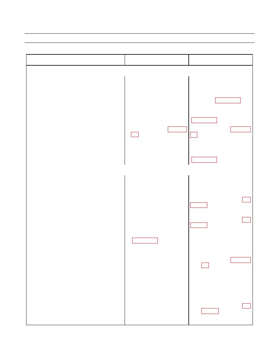
Table 4. Electrical System Troubleshooting Procedures - Continued. |
|
||
| ||||||||||
|
|
 TM 9-2320-312-24-1
TROUBLESHOOTING PROCEDURES - CONTINUED
0006 00
Table 4. Electrical System Troubleshooting Procedures - Continued.
MALFUNCTION
TEST OR INSPECTION
CORRECTIVE ACTION
HORN AND BACKUP ALARM CIRCUIT - CONTINUED
2. Horn Does Not Sound.
1. Ensure "HORN" 15A circuit
Reset circuit breaker.
breaker is not tripped.
If multimeter indicates 12Vdc,
2. Use multimeter to check for
12Vdc at horn terminal, with
replace horn (WP 0089 00).
horn button pressed.
3. Use multimeter to check
Replace failed circuit breaker
"HORN" 15A circuit breaker.
Replace failed relay (WP 0095
4. Remove horn relay (WP 0095
relay internal circuit.
Repair or replace damaged or
5. Use multimeter to check
wires and connectors between
corroded wires and connectors
components of horn circuit.
INSTRUMENT PANEL GAUGES AND CONTROLS
1. Fuel Gauge Inoperative
1. Ensure "GAUGES" 10A
Reset circuit breaker.
circuit breaker is not tripped.
Tighten, repair or replace
2. Inspect wires at fuel tank
sending unit for looseness or
damaged or corroded wires (WP
corrosion.
Replace damaged instrument
3. Inspect front and rear of
instrument and warning light
and warning light cluster (WP
cluster for signs of damage.
Ensure harness connector is
securely connected to cluster
a. If voltage is present at
4. Use multimeter to check for
harness
connector,
12Vdc at instrument and
replace cluster (WP 0094
warning light cluster harness
connector.
b. If voltage is not present,
continue to check harness
between instrument panel
and fuel tank sending unit.
Replace or repair wires or
connectors found to be
corroded or damaged (WP
|
|
Privacy Statement - Press Release - Copyright Information. - Contact Us |