|
| |
TM 9-2320-304-14&P
5-271
Direct Support and General Support Maintenance (Cont)
NOTE
·
Make sure slider arm is deployed.
·
Both flip lock brackets are adjusted
the same way. Right side shown.
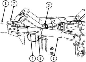
(16) Remove quick release pin (3) and
pin (4) from short strut (5) and long
strut (2).
(17) Using handle of arm assembly (6),
rotate arm assembly out and separate
short strut (5) from long strut (2).
(18) Holding arm assembly (6) out, Soldier
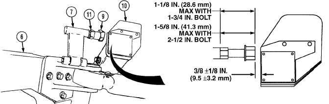
A positions flip lock (7) up.
(19) Soldier B measures gap between stop bolt (9) and right rear roller bracket (10).
NOTE
·
If gap is not 3/8 ±1/8 in. (9.5 ±3.2 mm), perform steps (20) and (21).
·
If gap is 3/8 ±1/8 in. (9.5 ±3.2 mm), go to step (22).
·
If dimension of gap is greater than 1.25 in. (3.18 cm) following adjustment, or proper
adjustment cannot be done, replace stop bolt with 2.50-in. (6.4 cm) long stop bolt.
(20) Loosen jam nut (11) and adjust stop bolt (9) as required.
(21) Tighten jam nut (11) on stop bolt (9).
(22) If proper adjustment could not be made, repeat steps (18) through (21) using longer bolt.
Change 1
|