 |
|||
|
|
|||
|
Page Title:
Torque Converter Module Disassembly - Continued |
|
||
| ||||||||||
|
|
 TM 9-2320-303-24-2
TRANSMISSION OVERHAUL - CONTINUED
0248 00
MODULE OVERHAUL - CONTINUED
Torque Converter Module Disassembly - Continued
12.
Remove thrust plate (24) from stator assembly (19). Measure, note, and tag thrust plate. Minimum thickness allowed is
0.372 in (9.45 mm).
13.
Remove thrust washer (23) from stator assembly (19).
14.
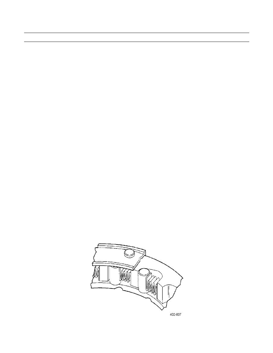
Remove stator race (22), 13 springs (20), and rollers (21). Inspect components for damage.
15.
Remove 44 bolts (11) securing lockup clutch backup plate (9) to cover assembly (2). Remove backup plate from cover.
16.
Measure thickness of backup plate wear surface. Minimum thickness allowed is 0.464 in (11.79 mm). Check for backup
plate distortion. Maximum distortion allowed is 0.006 in (0.15 mm).
17.
Remove lockup clutch damper assembly (8) from cover assembly (2). Perform the following measurements.
a.
Lockup clutch thickness: minimum thickness allowed is 0.335 in (8.51 mm).
b.
Lockup clutch distortion: maximum allowable distortion is 0.020 in (0.51 mm).
c.
Spline wear check: measure between turbine and lockup clutch damper. Maximum allowable wear is 0.015 in
(0.38 mm) on either spline.
18.
Remove lockup clutch piston (5), inner seal ring (4), and outer seal ring (7) from cover assembly (2). Measure thickness
of lockup clutch piston. Minimum thickness allowed is 0.257 in (6.53 mm).
19.
Inspect and measure inside diameter (ID) of converter cover bushing (3). Maximum allowed inside diameter of bushing
is 2.634 in (66.90 mm). Remove bushing if replacement is necessary.
20.
Remove thrust bearing (10) from converter cover (2).
Torque Converter Module Assembly
1.
Install stator race (22) into stator assembly (19).
2.
Install 13 springs (20) and rollers (21) into stator assembly (19). Use petrolatum to help hold springs and rollers in place.
0248 00-11
|
|
Privacy Statement - Press Release - Copyright Information. - Contact Us |
