 |
|||
|
|
|||
|
Page Title:
ELECTRICAL CONNECTORS MAINTENANCE |
|
||
| ||||||||||
|
|
 TM 9-2320-303-24-1
ELECTRICAL CONNECTORS MAINTENANCE
THIS WORK PACKAGE COVERS
Standard Military Connector Repair, Commercial Connector Repair, Splicing
INITIAL SETUP
Materials/Parts
Tools and Special Tools
Flux, soldering (Item 19, WP 0312 00)
Tool kit, general mechanic's (Item 102, WP 0313
Solder (Item 40, WP 0312 00)
Tags, marker (Item 42, WP 0312 00)
Tool kit, electrical connector repair (Item 101, WP
Equipment Condition
Harness, wiring (Item 32, WP 0313 00)
Master battery switch in OFF position (TM 9-2320-
303-10)
Heat gun (Item 33, WP 0313 00)
Soldering gun (Item 90, WP 0313 00)
References
TB SIG 222
Stripper, wire, hand (Item 94, WP 0313 00)
NOTE
Tag cables and wires to aid in installation.
STANDARD MILITARY CONNECTOR REPAIR
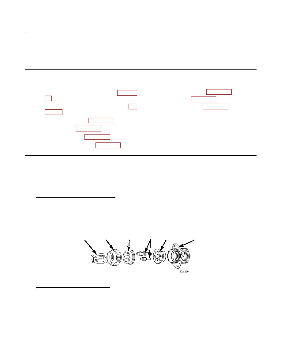
Panel Mounting Receptacle Disassembly.
1.
a.
Unscrew nut (2) from shell (6) assembly and slide back on cable leads (1).
b.
Push grommet (3) back on cable leads (1).
c.
Drive contacts (4) out through rear of insert (5) with pin extractor.
d.
Push insert (5) out through rear of shell (6).
e.
Unsolder cable leads (1) from contacts (4).
3
2
4
5
1
6
2.
Panel Mounting Receptacle Assembly.
a.
Strip cable insulation equal to depth of solder wells of contacts (4).
b.
Slide nut (2) over cable leads (1).
c.
Slide grommet (3) over cable leads (1).
d.
Insert cable leads (1) into solder wells of contacts (4) and solder.
e.
Push insert (5) into shell (6) from rear until seated. Groove in insert must be aligned with guide in shell to ensure
proper fit.
|
|
Privacy Statement - Press Release - Copyright Information. - Contact Us |