 |
|||
|
|
|||
|
Page Title:
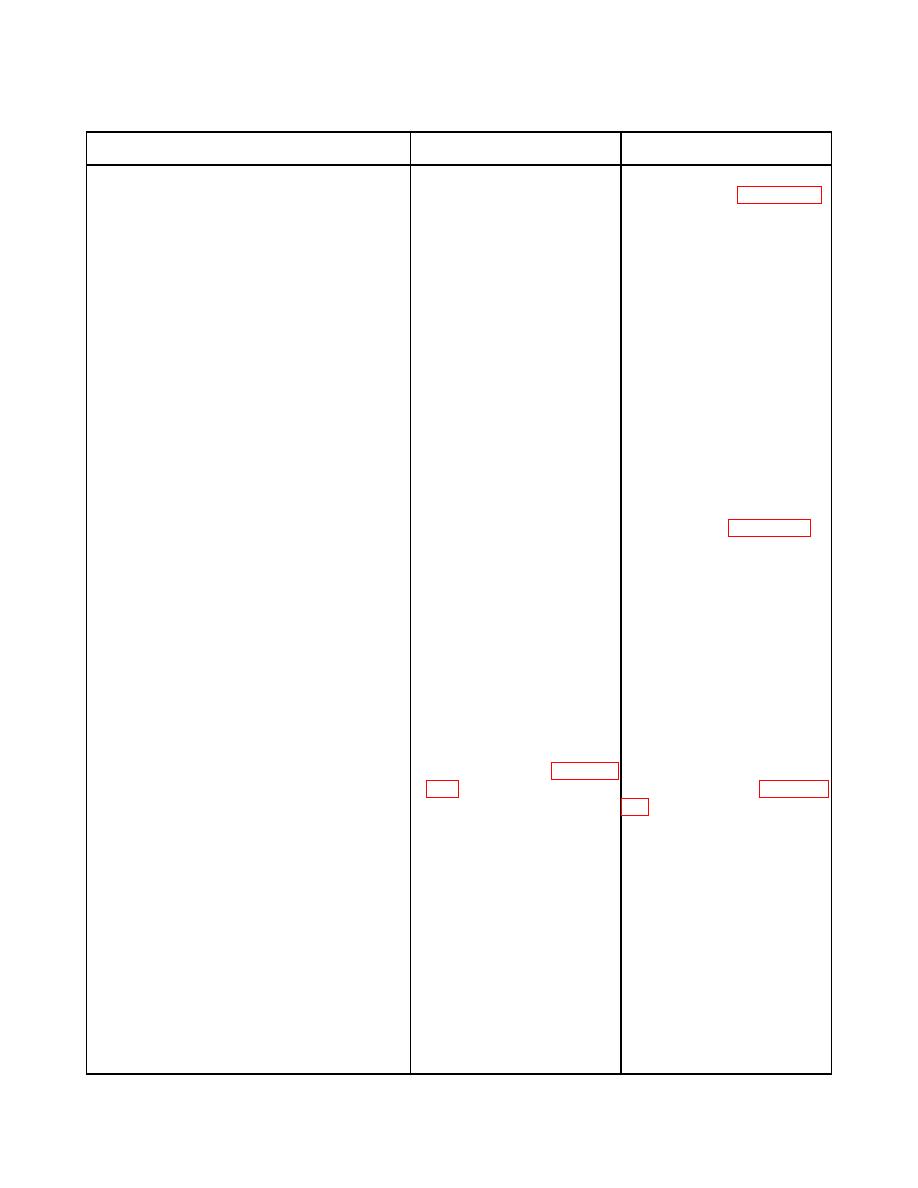
Table 1. Turn Signal and StopLight Circuits Troubleshooting Procedures. |
|
||
| ||||||||||
|
|
 TM 9-2320-303-24-1
Table 1. Turn Signal and StopLight Circuits Troubleshooting Procedures.
MALFUNCTION
TEST OR INSPECTION
CORRECTIVE ACTION
3.
Right Stoplight Not Operating - Continued.
4. Check for +24 VDC at turn If +24 VDC is present, replace
signal switch at lead 39B turn signal switch (WP 0070 00).
contact point.
If no voltage is present, repair lead
39B.
4.
None Of The Left Flasher Lights (24 V) 1. Inspect light bulbs.
Operating.
2. Disconnect left flasher relay If +24 VDC is present, go to step
from connector. Check for +24 3. If no voltage is present, repair
lead 421.
VDC at connector 30.
3. Check for continuity between If continuity is indicated, go to
connector 86 and ground.
step 4. If no continuity is
indicated, repair ground lead.
4. Check for +12
VDC
T If +12 VDC is present, go to step
connector 85.
5. If no voltage is present, repair
lead 60.
5. Set turn signal switch in left If +24 VDC is present, go to step
turn mode. Install jumper leads 6. If no voltage is present, replace
between connectors 30, 85, and left flasher relay (WP 0072 00).
86
to
their
respective
connectors at left flasher relay.
Check for +24 VDC at left
flasher relay connection 87.
6. Set turn signal switch in left
turn mode. Check for +24 VDC
at trailer receptacle connectors
421B.
5.
One Of The Left Turn Signal Lights Not 1. Inspect light bulb.
Operating.
2. Remove lamp from defective
If continuity is indicated, go to
left turn signal light (WP 0083
step 3. If no continuity is
indicated, replace lamp (WP 0083
between contact points.
3. Remove signal light lamp. If continuity is indicated, repair
Check for continuity between lead 60. If no continuity is
socket and ground.
indicated, repair ground lead.
6.
Left Turn Signal Indicator Light Not 1. Inspect light bulb.
Operating,
Turn
Signals
Operating
Normally.
2. Disconnect lead 60A from If +24 VDC is present,
warning light bar. Check for troubleshoot warning light circuit.
+24 VDC at lead 60A.
If no voltage is present, repair lead
60A.
|
|
Privacy Statement - Press Release - Copyright Information. - Contact Us |
