 |
|||
|
|
|||
|
|
|||
| ||||||||||
|
|
 TM 5-2420-224-34
BRAKE PRESSURE REGULATOR (ALB VALVE) ADJUSTMENT (CONT)
ADJUSTMENT
NOTE
For fail-safe adjustment, rear axle
load must be released.
1.
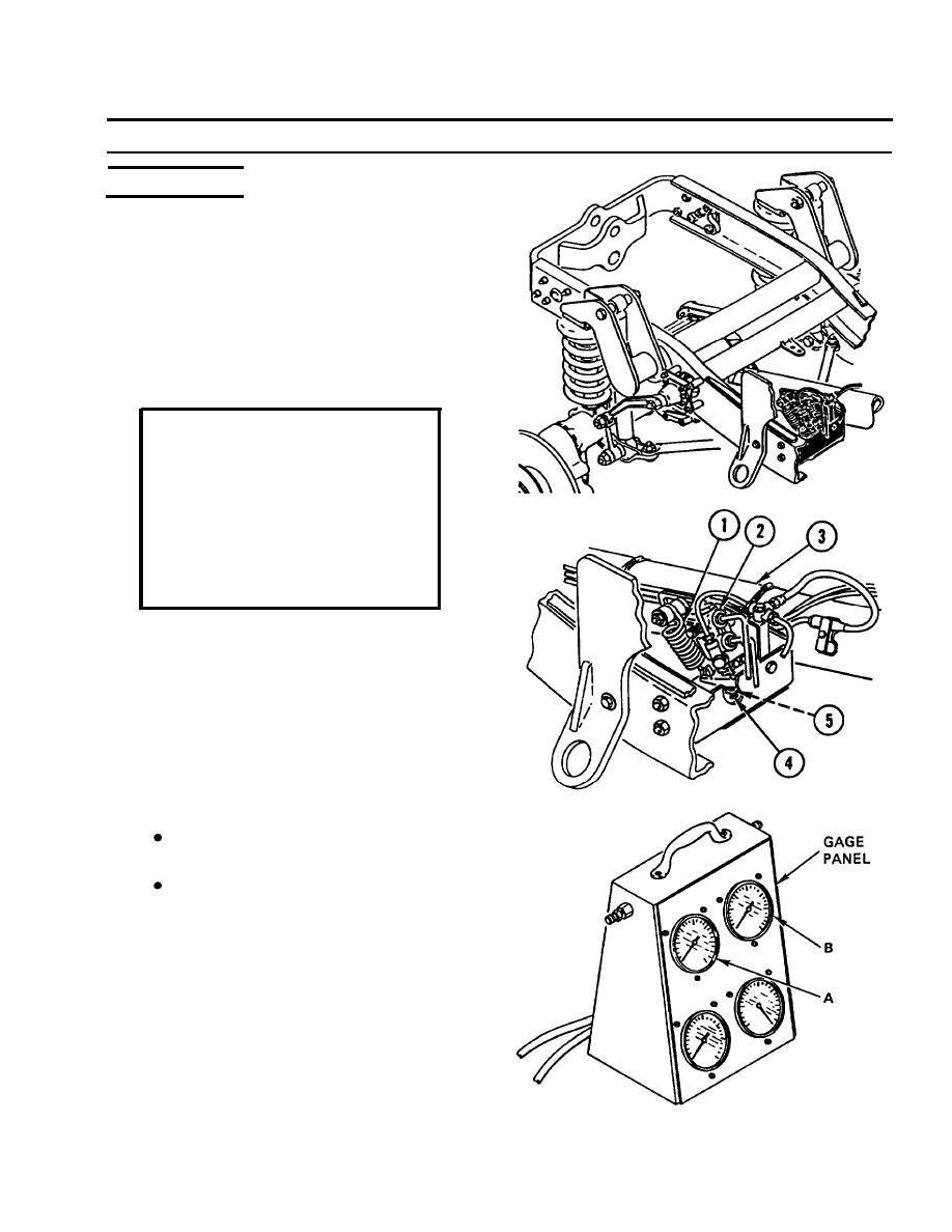
To release rear axle load, remove control
spring (1) connecting ALB valve (2) to rear
torque tube (3), or use backhoe (SEE) or
crane (HMMH) outriggers to raise rear tires
completely off the ground.
CAUTION
A f t e r spring tension has been
released,
make sure
air
pressure of vehicle brake
s y s t e m is not below 90 psi (6
bar) as indicated on air
pressure gage located on
instrument panel to prevent
d a m a g e to equipment.
Position gage panel so gages can be read
2.
accurately. Slowly press brake pedal until full
b r a k e pedal pressure is achieved. Both
pressure gages should rise until gage A reads
modulated fall-safe pressure setting of 515 psi
(35 bar). Tolerance of 44 psi (3 bar) is
permissible. Gage B of unmodulated circuit
should read approximately 1924-2072 psi
(130-140 bar).
NOTE
Pressure of gage A must be set
to 515 psi (35 bar).
Do not apply brake pedal
p r e s s u r e while adjusting ALB
valve.
To obtain setting for gage A, adjust screw (4)
3.
on ALB valve (2) as necessary. Tolerance of
44 psi (3 bar) is permissible.
4.
Loosen retainer lock nut (5) and turn screw
(4) clockwise to increase pressure or
counterclockwise to decrease pressure, to
obtain required setting. Tighten retainer lock
nut.
7-7
|
|
Privacy Statement - Press Release - Copyright Information. - Contact Us |