 |
|||
|
|
|||
|
|
|||
| ||||||||||
|
|
 TM 5-2420-224-34
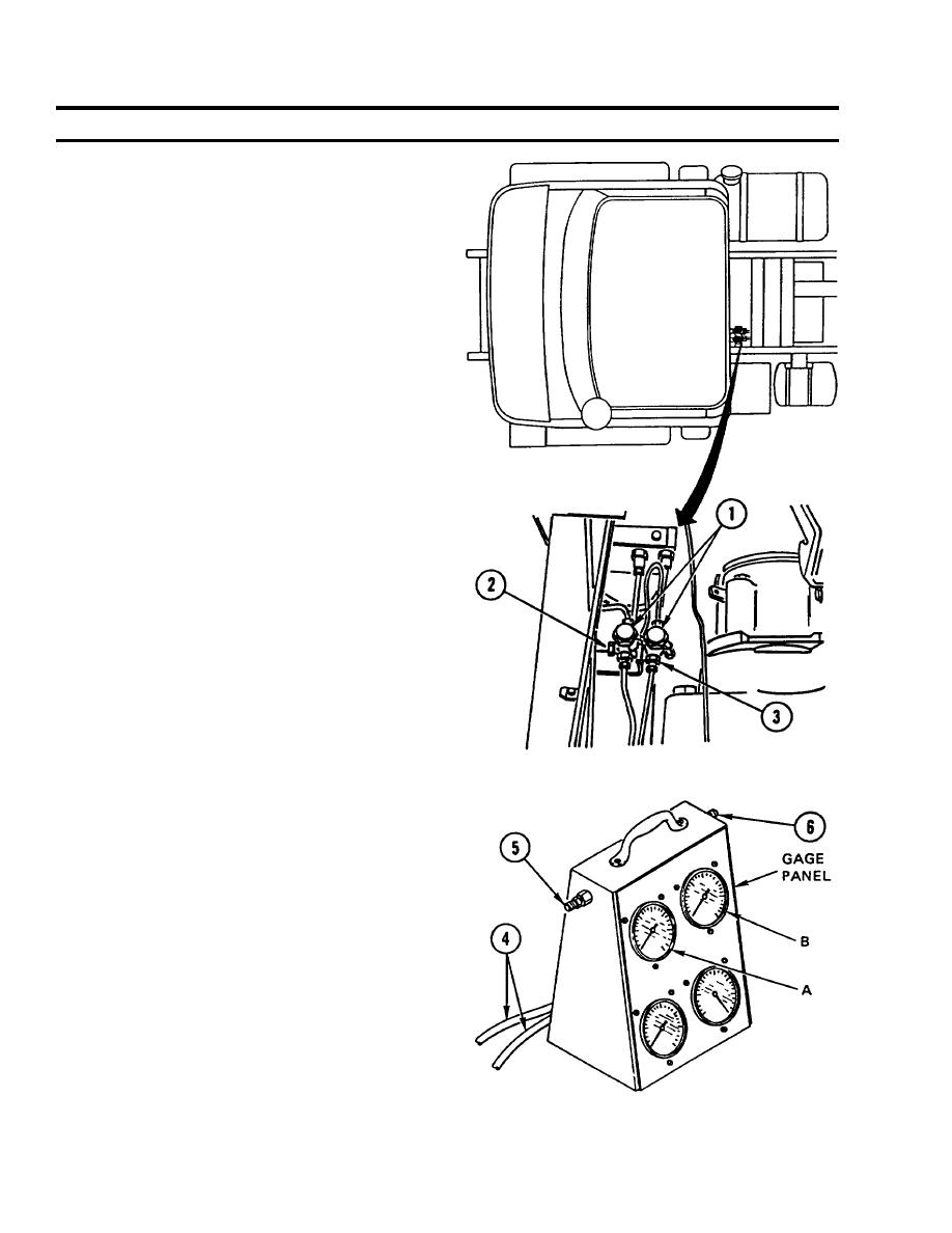
BRAKE PRESSURE REGULATOR (ALB VALVE) ADJUSTMENT (CONT)
R E M O V E BACKHOE (SEE) or CRANE
5.
( H M M H ) from TRANSPORT position and
PLACE in WORK position (TM 5-2420-224-
10).
REMOVE two CAPS (1) from test connections
6.
(2 and 3).
INSTALL two male quick-coupler FlTTINGS
7.
provided with gage panel.
CONNECT two pressure gage HOSES (4) to
8.
test connections as follows:
a. PLACE pressure gage HOSE from
GAGE
A
of
GAGE
PANEL
to
C O N N E C T I O N of CIRCUIT 1 (2) of
vehicle MODULATED test port.
b. PLACE pressure gage HOSE from
GAGE B of GAGE PANEL to
C O N N E C T I O N of CIRCUIT 2 (3)
vehicle UNMODULATED test port.
TESTING
Purge/bleed pressure gage at two bleed port
1.
fittings (5 and 6) located on each side of
gauge by pressing brake pedal several times.
While pressing brake pedal to full actuation
2.
(floor) and holding, open bleed port (5) on left
side of gage panel for gage A. Close bleed
port (5) for gage A.
Repeat until there is steady, clear flow of
3.
brake fluid.
Repeat procedure for right side of gage panel
4.
by bleeding port (6) for gage B.
After purging/bleeding gages, gage panel is
5.
ready to be used to adjust ALB valve.
7-6
|
|
Privacy Statement - Press Release - Copyright Information. - Contact Us |
