 |
|||
|
|
|||
|
|
|||
| ||||||||||
|
|
 TM 5-2420-224-34
Table 2-1. Troubleshooting (Cont)
Malfunction
Test or Inspection
Corrective Action
HYDRAULIC SYSTEM (CONT)
NOTE
The 0-5000 psi (0-345 bar) pressure gage must be calibrated. If not, performance of front
loader/forklift circuits and tool circuits will not be correct.
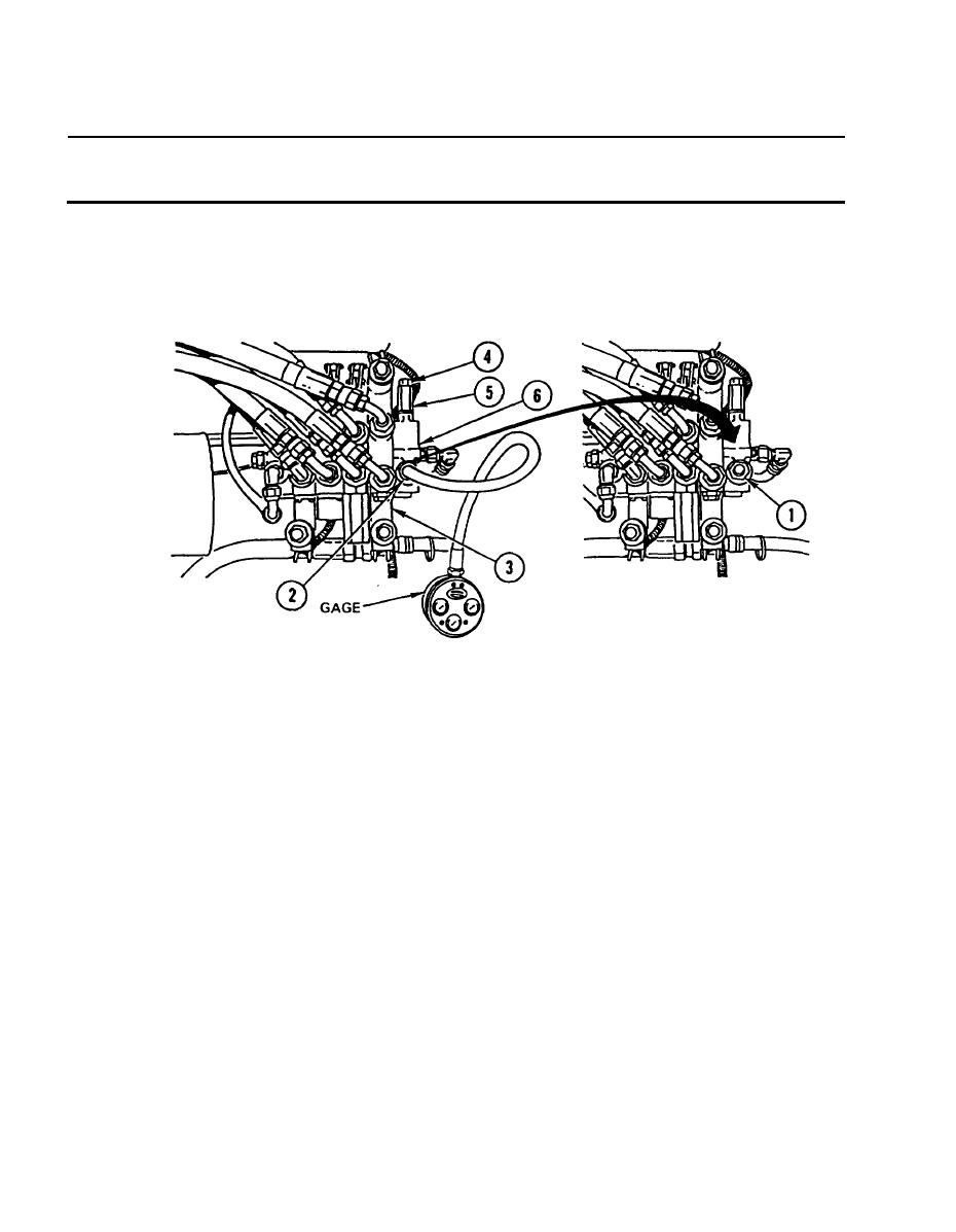
e. Connect 0-5000 psi (0-345 bar) pressure gage to fitting in inlet (2) of
control valve (3).
f.
Start and run engine at idle speed of 2000 rpm.
g. Move bucket control lever into rollback position and hold for 15 seconds;
then place lever in neutral for 30 seconds.
h. Repeat steps f and g until oil is at operating temperature of 120F (49C)
Keep engine running at 2000 rpm.
i.
Move bucket control tilt lever into rollback/tilt back position and read
j.
0-5000 psi (0-345 bar) pressure gage. Pressure reading must be 2450 psi
(169 bar).
If pressure reading is not 2450 psi (169 bar), repeat steps i and
j while holding bucket control lever in dump/forward tilt position.
If pressure reading is still not 2450 psi (169 bar), hold
adjusting screw (4) and loosen lock nut (5) on relief valve (6).
Turn adjusting screw (4) to right to increase pressure, or left to
decrease pressure. Hold adjusting screw (4), tighten lock nut
(5), and check 0-5000 psi (0-345 bar) pressure gage for
reading of 2450 psi (169 bar). Repeat as necessary.
If 2450 psi (169 bar) cannot be attained, go to step 3.
2-16
|
|
Privacy Statement - Press Release - Copyright Information. - Contact Us |
