Order this information in Print

Order this information on CD-ROM

Download in PDF Format


Click here to make tpub.com your Home Page

Page Title: ADJUSTMENT - CONTINUED
Back | Up | Next

Click here for a printed version

Google


Web
www.tpub.com

Home


Information Categories
.... Administration
Advancement
Aerographer
Automotive
Aviation
Combat
Construction
Diving
Draftsman
Engineering
Electronics
Food and Cooking
Math
Medical
Music
Nuclear Fundamentals
Photography
Religion
USMC
   
Products
  Educational CD-ROM's
Printed Manuals
Downloadable Books


TM 5-2420-222-20-2 
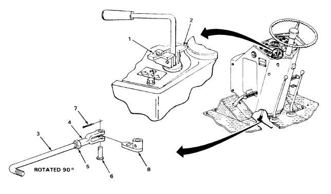
SPEED GEAR ASSEMBLY (REVERSER) CONTROL LEVER LINKAGE - CONTINUED ACTION LOCATION ITEM REMARKS 70. Pin (6) Cotter pin (7) a. Push in. b. Using slip-joint pliers bend ends back. 71. Link (3) and Nut (5) If loose, using 1/2-inch open-end wrench adjustable yoke (4) and 0 to 1.322-inch adjustable wrench, tighten until seated against yoke (4). NOTE FOLLOW-ON MAINTENANCE: 1. Install center platform support (page 2-1106). 2. Install right inner platform ramp (page 2-1095). 3. Install right platform (page 2-1079). 4. Install left outer platform ramp (page 2-1073). 5. Install left platform (page 2-1060). TASK ENDS HERE TA243123 2-827

Privacy Statement - Press Release - Copyright Information. - Contact Us - Support Integrated Publishing

Integrated Publishing, Inc. - A (SDVOSB) Service Disabled Veteran Owned Small Business