Order this information in Print

Order this information on CD-ROM

Download in PDF Format


Click here to make tpub.com your Home Page

Page Title: ADJUSTMENT - CONTINUED
Back | Up | Next

Click here for a printed version

Google


Web
www.tpub.com

Home


Information Categories
.... Administration
Advancement
Aerographer
Automotive
Aviation
Combat
Construction
Diving
Draftsman
Engineering
Electronics
Food and Cooking
Math
Medical
Music
Nuclear Fundamentals
Photography
Religion
USMC
   
Products
  Educational CD-ROM's
Printed Manuals
Downloadable Books


TM 5-2420-222-20-2 
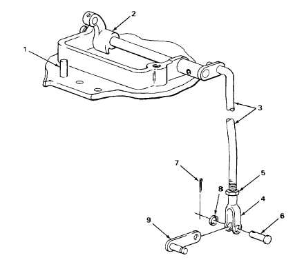
SPEED GEAR ASSEMBLY (REVERSER) CONTROL LEVER LINKAGE - CONTINUED ACTION LOCATION ITEM REMARKS 56. Clutch control Yoke (4) Place in position. valve shaft (9) 57. Clutch control Headed pin (6) a. Put in. valve shaft (9) b. Repeat steps 47 thru 55 until clearance and yoke (4) meets specification. NOTE If   lockwasher   and   cotter   pin   have   just   been   replaced   during   assembly,   they   may   be   reused   after adjustment.  Otherwise, use new lockwasher and cotter pin. 58. Headed pin (6) Washer (8) Put on. 59 Cotter pin (7) a. Push in. b. Using slip-joint pliers, bend ends back. 60. Control lever Nut (5) Using 9/16-inch open-end wrench and 0 to rod (3) and 1.322-inch adjustable wrench, tighten yoke (4) until seated against yoke (4). TA243122 2-825

Privacy Statement - Press Release - Copyright Information. - Contact Us - Support Integrated Publishing

Integrated Publishing, Inc. - A (SDVOSB) Service Disabled Veteran Owned Small Business