Order this information in Print

Order this information on CD-ROM

Download in PDF Format


Click here to make tpub.com your Home Page

Page Title: TM-5-2420-222-20-2_392
Back | Up | Next

Click here for a printed version

Google


Web
www.tpub.com

Home


Information Categories
.... Administration
Advancement
Aerographer
Automotive
Aviation
Combat
Construction
Diving
Draftsman
Engineering
Electronics
Food and Cooking
Math
Medical
Music
Nuclear Fundamentals
Photography
Religion
USMC
   
Products
  Educational CD-ROM's
Printed Manuals
Downloadable Books


TM 5-2420-222-20-2 
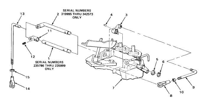
SPEED GEAR ASSEMBLY (REVERSER) CONTROL LEVER LINKAGE - CONTINUED ACTION LOCATION ITEM REMARKS 19. Shaft (1) Control lever a. Take off. arm (11) b. Take shaft (1) out of machinist’s vise. 20. Control lever rod Nut (15) a. Place rod (13) in machinist’s vise. (13) and yoke (14) b. Using 9/16-inch open-end wrench, loosen. 21. Control lever Yoke (14) and a. Note number of exposed threads on rod (13) nut (15) rod (13) and relative position of yoke (14). b. Unscrew and take off. c. Take rod (13) out of machinist’s vise. TA243119 2-819

Privacy Statement - Press Release - Copyright Information. - Contact Us - Support Integrated Publishing

Integrated Publishing, Inc. - A (SDVOSB) Service Disabled Veteran Owned Small Business