 |
|||
|
|
|||
|
|
|||
| ||||||||||
|
|
 TM5-241O-237-34
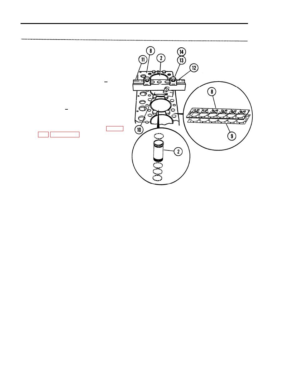
3-8. CYLINDER LINERS - REPLACE (Cont'd)
(10) If liner projection is not 0.0012
to 0.0069 inches, check thickness
of the spacer plate (8). Thicknes
must be 0.3925+0.0010 inches.
--
(11) Check thickness of gasket (9).
Thickness must be 0.0082 + 0.0010
inches.
(12) Recheck thickness of cylinder
liner flange (2). Thickness must
be 0.4048 + 0.0008 inches.
(13) If the measurements taken in
STEPS 8 through 12 agree with the
specifications (refer to Table
projection changes from point to
point around the liner, or if any
of the mentioned parts are
replaced and liner projection is
still not correct, turn the liner
to a new position within the
bore. If correct projection is
achieved this way, put an
alignment mark on the liner and
the block. This will ensure
correct liner placement at
If projection
installation.
cannot be corrected this way,
move the liner to a different
bore and repeat previous STEPS 4
through 7 and STEP 13. If correct
projection is accomplished, put a
liner-to-block alignment mark on
both parts to ensure correct
liner position at installation.
(14) If correct cylinder liner
projection cannot be accomplished
using the preceding procedure,
adjustment will have to be done
by machining the contact face of
the cylinder block.
(15) Remove liner projection tool
puller crossbar (11), and
adapter plate (10).
(16) Remove cylinder liner (2),
spacer plate (8) and gasket (9).
3-28
|
|
Privacy Statement - Press Release - Copyright Information. - Contact Us |
