 |
|||
|
|
|||
|
|
|||
| ||||||||||
|
|
 TM5-241O-237-34
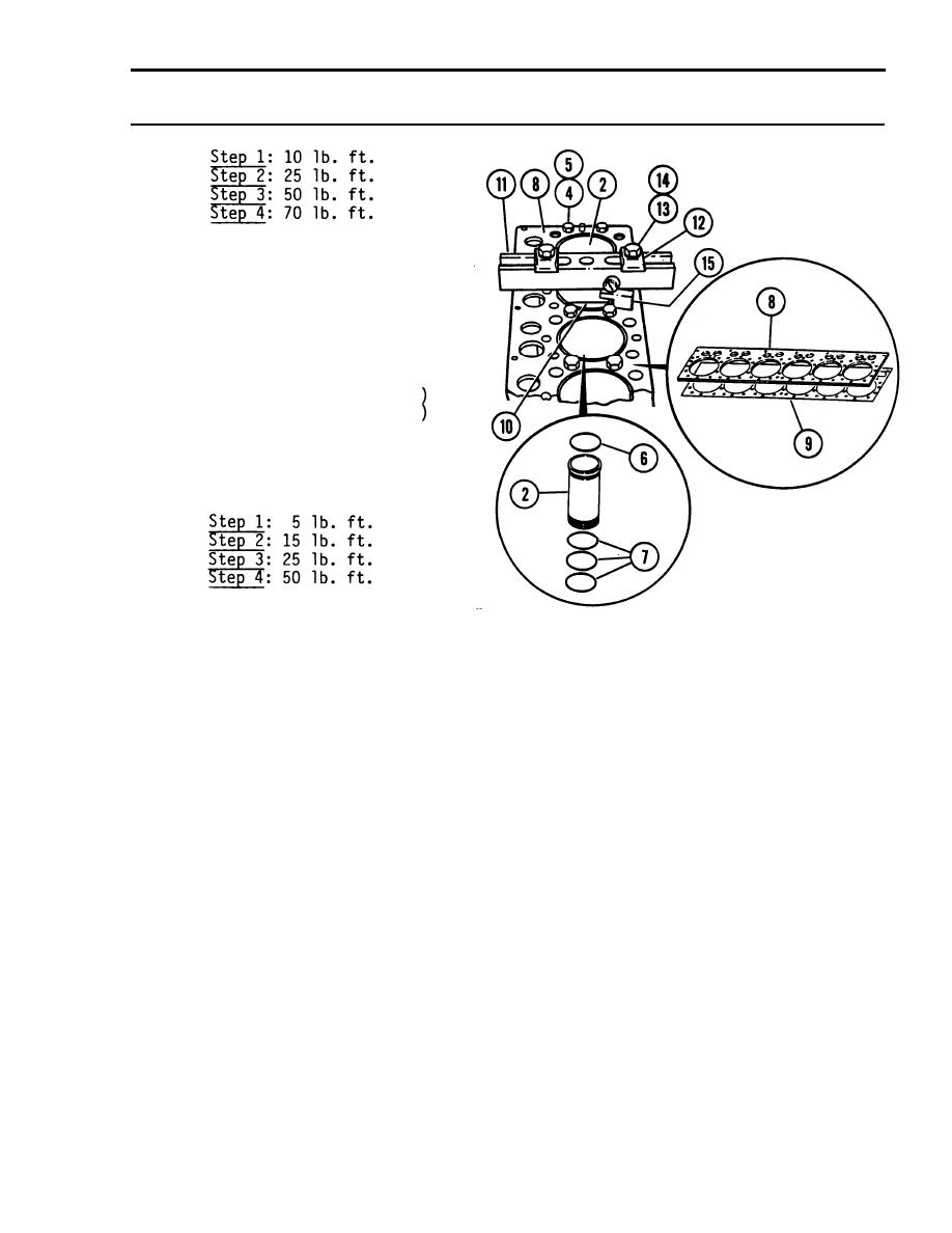
3-8. CYLINDER LINERS - REPLACE (Cont'd)
(4) Install cylinder liners (2),
without packings (6) and filler
bands (7), through the spacer
plate (8) and gasket (9) and
into the block.
(5) Put adapter plate (10) on the
cylinder, then install puller
crossbar (11), plates (12, and
5/8-11 X 6" capscrews (13 and
21/32 ID flat washers (14).
(6) Tighten capscrews (13) evenly, in
four steps, as follows:
The measurement, from the bottom
of the crossbar-(n) to the spacer
plate (8), must be the same on
both sides of the cylinder liner
(2).
(7) Check cylinder liner projection
with a Liner Projection Tool
(15). Measure as close as
possible to the four corners of
the adapter plate (10).
(8) Record the four measurements as
they will be needed as reference
data later.
(9) Liner projection must be 0.0012
to 0.0069 inches. Measurements
on the same liner must not be
different by more than 0.002
inches. The difference in the
average cylinder liner projection
between adjacent liners must not
be more than 0.002 inches.
3-27
|
|
Privacy Statement - Press Release - Copyright Information. - Contact Us |
