 |
|||
|
|
|||
|
|
|||
| ||||||||||
|
|
 TM 5-2410-237-23
CYLINDER LINERS REPLACEMENT - CONTINUED
0245 02
PROJECTION CHECK - CONTINUED
5.
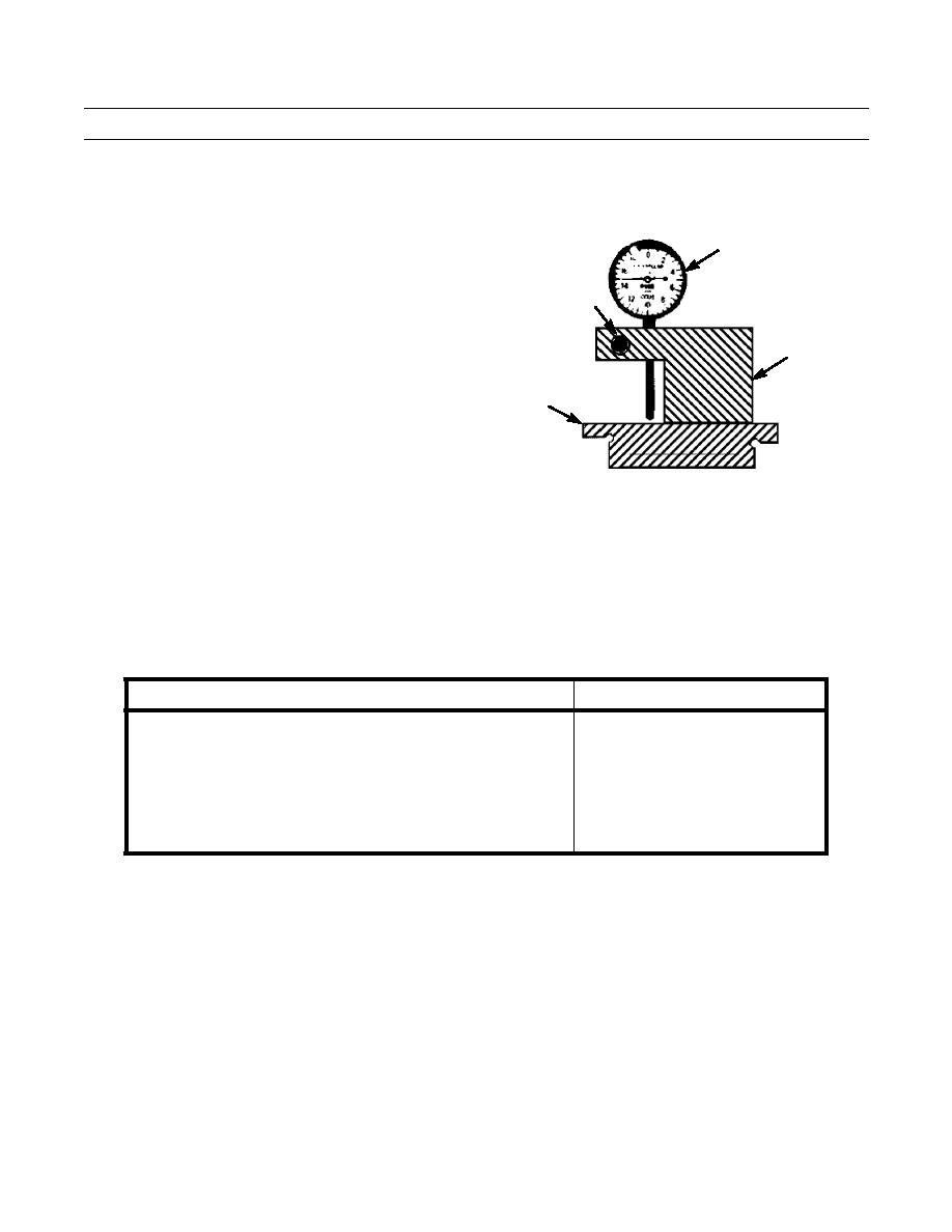
Loosen bolt (11) until dial indicator (12) can be
moved. Place gage body (13) and dial indicator on
long side of gage (14).
12
6.
Slide dial indicator (12) into position until point
touches gage (14). Slide dial indicator until needle of
dial indicator makes 1/4 revolution to the right. Needle
11
should be in a vertical position. Tighten bolt (11) to
secure dial indicator.
13
14
421-0020
7.
Place gage body (13) on spacer plate (6) with dial indicator point on cylinder liner flange. Read dial indicator to find
amount of cylinder liner projection. Record measurement.
8.
Check cylinder liner projection at four locations, every 90 degrees around each cylinder liner. Record measurements.
9.
Refer to Table 2, to determine if readings taken in steps 7 and 8 are within specification.
Table 2. Cylinder Liner Projection Specifications.
DESCRIPTION
SPECIFICATION
Liner Projection
0.0013-0.0069 in.
(0.033-0.175 mm)
Maximum variation in each cylinder
0.0020 in. (0.051 mm)
Maximum average variation between adjacent cylinders
0.0020 in. (0.051 mm)
Maximum variation between all cylinders
0.0040 in (0.102 mm)
0245 02-5
Change 1
|
|
Privacy Statement - Press Release - Copyright Information. - Contact Us |
