 |
|||
|
|
|||
|
|
|||
| ||||||||||
|
|
 TM 5-2410-237-23
RIPPER SHANK REPLACEMENT - CONTINUED
0240 00
REMOVAL - CONTINUED
NOTE
Use lifting device to take pressure off pin.
When removing center shank, remove cotter pins and retainers from both ends of pin. Push pin to the
right so that end of pin enters hole in ripper beam brace.
4.
Remove cotter pin (4) and retainer (5) from one end of pin (6). Discard cotter pins.
5.
Drive pin (6) from beam (2) and shank (3).
6.
Lower lifting equipment until shank (3) is resting on ground.
INSTALLATION
1.
Position shank (3) under beam (2).
NOTE
If installing on a hard surface, remove tooth (7) for clearance (WP 0239 00). If installing on a soft surface, a
small hole about 10 in. (25.4 cm) deep can be dug to provide enough clearance.
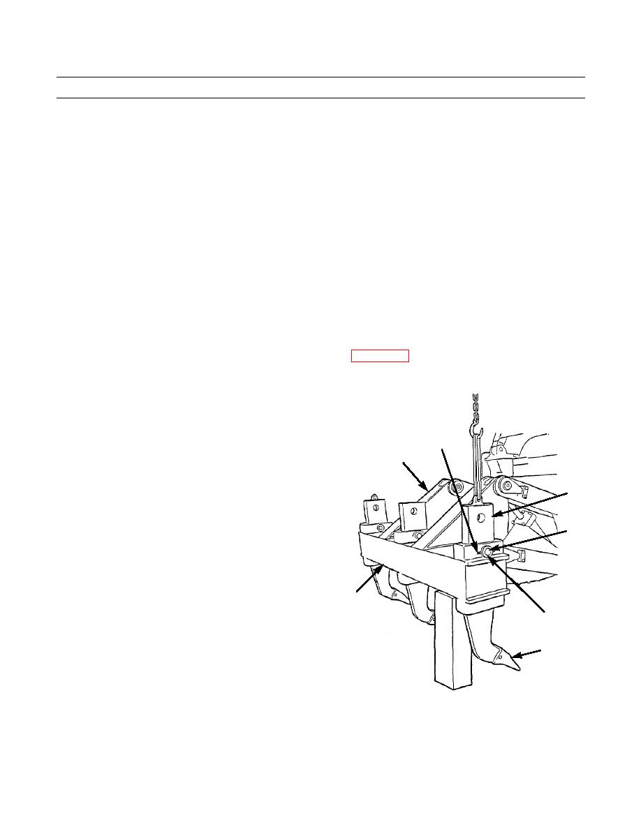
2.
Attach a nylon sling and a suitable lifting device to
lifting eye in shank (3). Feed sling through hole in bot-
tom of beam (2).
3.
Lift shank (3) into position and insert pin (6). Drive
4
pin through beam (2) and shank (3).
1
4.
Install retainers (5) on both ends of pin (6). Align
holes in retainers and pin, and install new cotter pin
(4) at each end of pin.
3
5.
Start engine, raise ripper and remove block(s).
6.
Remove nylon sling and lifting device from shank (3).
6
7.
Check ripper for proper operation.
8.
Lower ripper and shut down engine (TM 5-2410-237-
10).
2
5
7
387-386
END OF WORK PACKAGE
0240 00-2
|
|
Privacy Statement - Press Release - Copyright Information. - Contact Us |
