 |
|||
|
|
|||
|
|
|||
| ||||||||||
|
|
 TM 5-2410-237-23
WINCH ASSEMBLY PRESSURE TESTS - CONTINUED
0190 01
PRESSURE TESTS
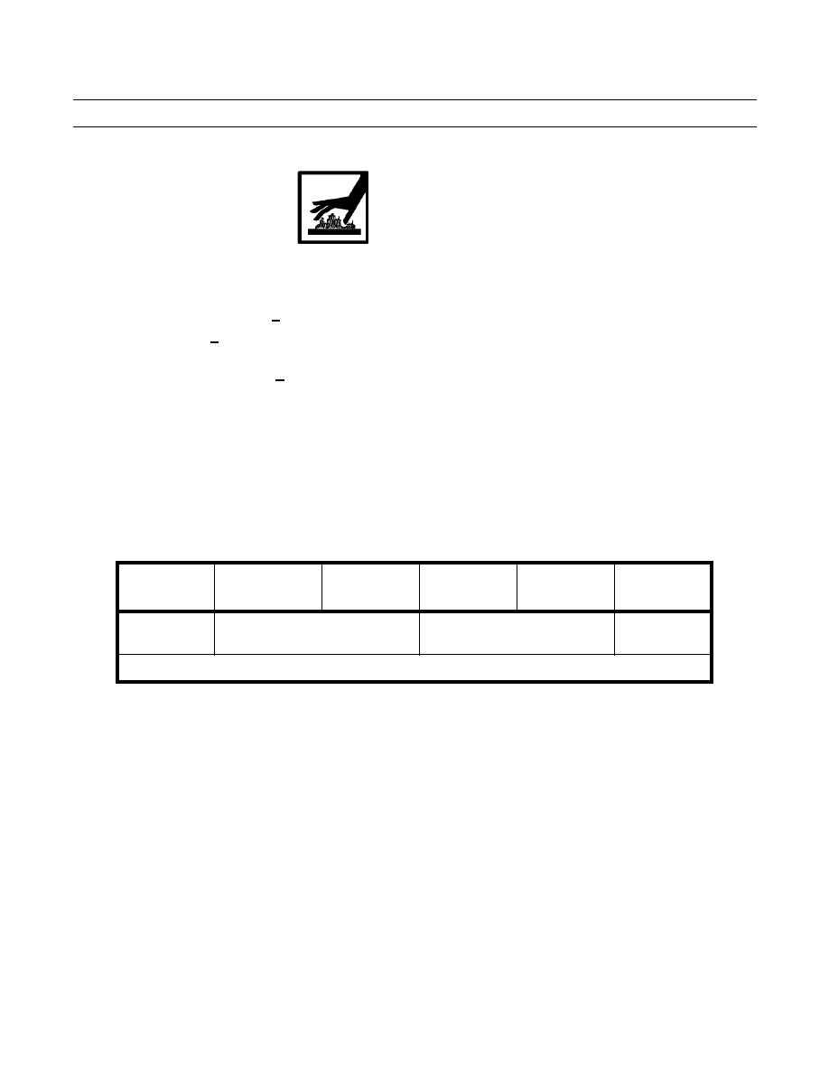
WARNING
At operating temperature winch oil is hot. Wear hand protection during pressure testing. Failure to do so
could result in injury.
1.
Start engine (TM 5-2410-237-10).
2.
Run engine at high idle (2100 + 30 RPM) with winch control lever in BRAKE ON position (TM 5-2420-237-10).
3.
At high idle (2100 + 30 RPM), gage reading at pressure tap (3) must be approximately 40 psi (276 kPa). Gage readings
at pressure taps (1 and 2) must be 0 psi (0 kPa).
4.
With engine at high idle (2100 + 30 RPM), pull winch control lever slowly in the direction of BRAKE OFF position.
a.
Gage reading at pressure tap (1) must go up immediately until it is 250 15 psi (1724 103 kPa).
b.
Gage reading at pressure tap (2) must become larger with any force increase on control lever. Maximum gage read-
ing at pressure tap (2) must be 250 15 psi (1724 103 kPa).
c.
Maximum gage reading at pressure tap (1) must be approximately 250 psi (1724 kPa).
5.
With winch control lever in BRAKE OFF position, operate engine at low idle and record pressures at pressure taps (1, 2
and 3). Pressure readings should be as indicated in Table 1.
Table 1. Low Idle Pressures.
LEVER
PUMP
INPUT
REEL IN
REEL OUT
LUBE (3)
POSITION
PRESSURE (1)
CLUTCH (1)
CLUTCH (2)
CLUTCH (2)
BRAKE OFF
230 psi minimum
220 psi minimum
*40 psi
(1586 kPa minimum)
(1517 kPa minimum)
(276 kPa)
*NOTE. During time of pressure increase at taps (1 and 2), reading at tap (3) can be near 0 psi (0 kPa).
6.
Move winch control lever to BRAKE ON position. Winch drum must not rotate.
7.
Shut down engine (TM 5-2410-237-10).
8.
If pressure test results are OK, proceed to Restoring Equipment.
9.
If pressure test results are NOT OK, refer to Interpreting Test Results at the end of this work package to determine prob-
able cause of problem.
0190 01-3
Change 1
|
|
Privacy Statement - Press Release - Copyright Information. - Contact Us |