 |
|||
|
|
|||
|
|
|||
| ||||||||||
|
|
 TM 5-2410-237-23
STEERING BRAKE HYDRAULIC CONTROL ASSEMBLY MAINTENANCE - CONTINUED
0151 00
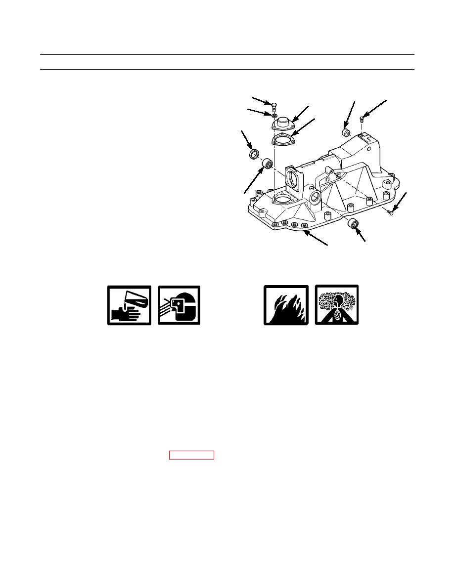
DISASSEMBLY - CONTINUED
24.
Remove seal (95) and two bearings (96) from shaft
98
97
102
100
mounting holes in hydraulic control (12). Discard seal.
99
101
25.
Turn hydraulic control (12) to open side down.
95
26.
Remove seal (97) from parking brake lever assembly
hole in hydraulic control (12). Discard seal.
27.
Remove three capscrews (98), lockwashers (99), cover
(100) and gasket (101) from end of hydraulic control
(12). Discard lockwashers and gasket.
28.
Remove plug (102) from top of hydraulic control (12).
103
29.
Remove plug (103) from side of hydraulic control
96
(12).
387-715
96
12
CLEANING
WARNING
Solvent cleaning compound MIL-PRF-680 Type III is an environmentally compliant and low toxic
material. However, it may be irritating to the eyes and skin. Use protective gloves and goggles. Use in
well-ventilated areas. Keep away from open flames and other sources of ignition.
Particles blown by compressed air are hazardous. DO NOT exceed 15 psi (103 kPa) nozzle pressure
when drying parts with compressed air. Use a maximum of 30 psi (207 kPa) when cleaning compo-
nents. DO NOT direct compressed air against human skin. Failure to follow this warning may result in
serious injury or death. Make sure air stream is directed away from user and other personnel in the
area. To prevent injury, user must wear protective goggles or face shield.
1.
Clean all removed components with solvent cleaning compound.
2.
Thoroughly dry components with compressed air or clean rags.
3.
Remove all old gasket material from mounting flange of hydraulic control and mounting surface on top of gear case.
INSPECTION
1.
Inspect all removed components IAW (WP 0241 00).
2.
Replace any component found to be damaged.
0151 00-10
|
|
Privacy Statement - Press Release - Copyright Information. - Contact Us |
