 |
|||
|
|
|||
|
|
|||
| ||||||||||
|
|
 TM 5-2410-237-23
STEERING BRAKE HYDRAULIC CONTROL ASSEMBLY MAINTENANCE - CONTINUED
0151 00
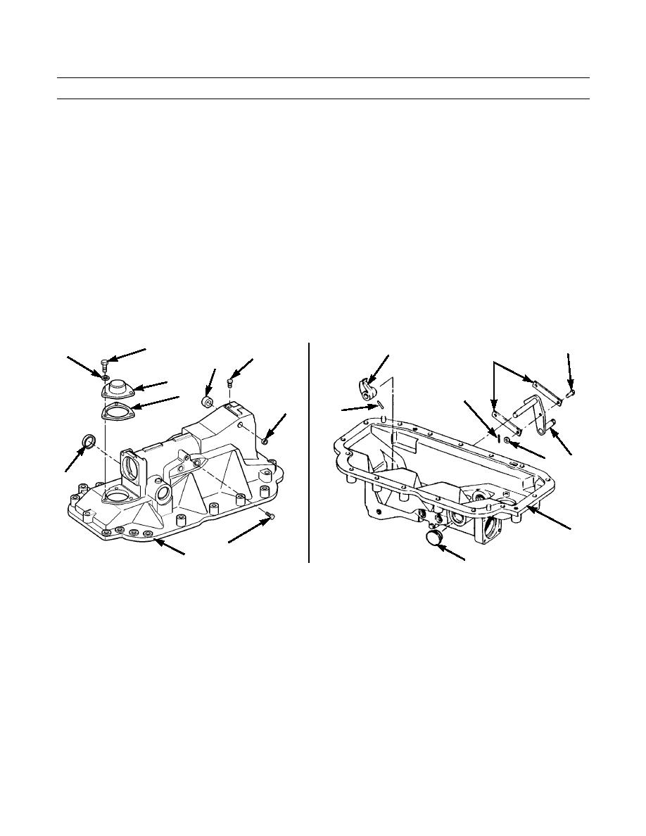
ASSEMBLY
CAUTION
Care should be taken not to contaminate steering brake system during assembly of hydraulic control. Dirt
and foreign substances should be removed from surrounding area.
1.
Install plug (103) on side of hydraulic control (12).
2.
Install plug (102) in top of hydraulic control (12).
3.
Wipe gasket surface on cover (100) and hydraulic control (12) clean. Install new gasket (101) and cover on hydraulic
control with three new lockwashers (99) and capscrews (98).
4.
Apply a light film of clean lubricating oil to lip of new seal (97). Insert seal, lip first, into hole for parking brake lever
shaft. Ensure seal in fully seated in hole.
5.
Install new plug (94) in lever shaft hole on opposite side of hydraulic control (12).
6.
Repeat steps 4 and 5 to install new seal (95) and new plug (71) for large shaft holes in hydraulic control (12).
7.
Turn hydraulic control (12) to open side up.
98
89
93
99
102
90
97
100
101
87
94
92
91
88
95
12
103
387-716
12
71
387-720
8.
Insert shaft of parking brake lever assembly (91) through seal (97) in hydraulic control (12) and through pawl (93) into
hole in opposite side of hydraulic control.
9.
Line up hole in pawl (93) with hole in parking brake lever assembly (91) and install pin (92).
10.
Install two links (90) to parking brake lever assembly (91) with pin (89), washer (88) and new cotter pin (87).
0151 00-11
|
|
Privacy Statement - Press Release - Copyright Information. - Contact Us |
