 |
|||
|
|
|||
|
|
|||
| ||||||||||
|
|
 TM 5-2410-237-23
STEERING BRAKE PEDALS AND LINKAGE ADJUSTMENT - CONTINUED
0145 00
ADJUSTMENT - CONTINUED
4.
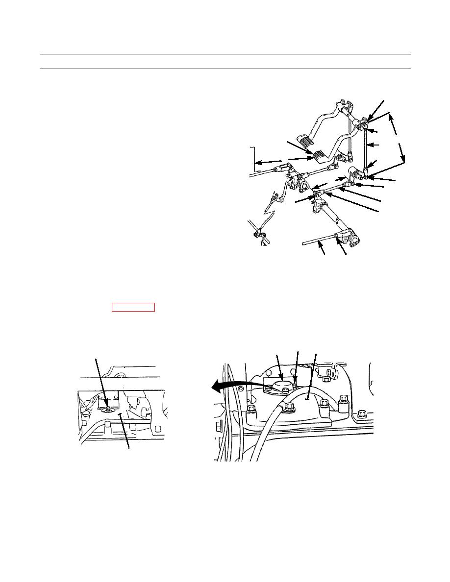
Remove rod (7) by removing two cotter pins (8) and
8,10
MOUNTED
pins (9 and 10). Discard cotter pins.
ON DASH
5.
Loosen nut (11) at both ends of rod (7) and turn rod
until distance between center line of pins (9 and 10) is
11
19.25 in. +/- 0.02 in. (48.90 cm +/- 0.05 cm) dimen-
18
C
sion C.
SEAT
7
KICK
PLATE
6.
Tighten nuts (11).
11
A
7.
Install rod (7) and secure with pins (9 and 10) and new
cotter pins (8).
8,9
B
15
8.
Loosen nut (12) on rod (13) and turn rod until distance
between center lines of pins (14 and 15) is 12.88 in.
14
13
(32.7 cm) dimension B.
MOUNTED
TO L.H.
12
ON FENDER
BRAKE
SUPPORT BEAM
9.
Tighten nut (12).
MOUNTED
ON SEAT
FRAME
10.
Loosen nut (16) on rod (17) and turn rod end to adjust
length of rod so distance between front of right brake
pedal (18) and seat kick plate is 18.53 in. +/- 0.12 in.
387-356
16
17
(47.07 cm +/- 0.30 cm) dimension A.
11.
Tighten nut (16).
12.
Install new gasket (4) and cover (3) with three washers (2) and capscrews (1).
13.
Repeat steps 1 through 12 for left side.
14.
Install floor plates (WP 0171 00).
15.
Turn battery disconnect switch to ON position (TM 5-2410-237-10).
16.
Test drive and check for proper operation (TM 5-2410-237-10).
1,2
5
3,4
6
5
387-355
END OF WORK PACKAGE
0145 00-2
|
|
Privacy Statement - Press Release - Copyright Information. - Contact Us |