 |
|||
|
|
|||
|
|
|||
| ||||||||||
|
|
 TM 5-2410-237-23
TRACK ROLLER FRAME ASSEMBLY REPLACEMENT - CONTINUED
0135 00
REMOVAL - CONTINUED
NOTE
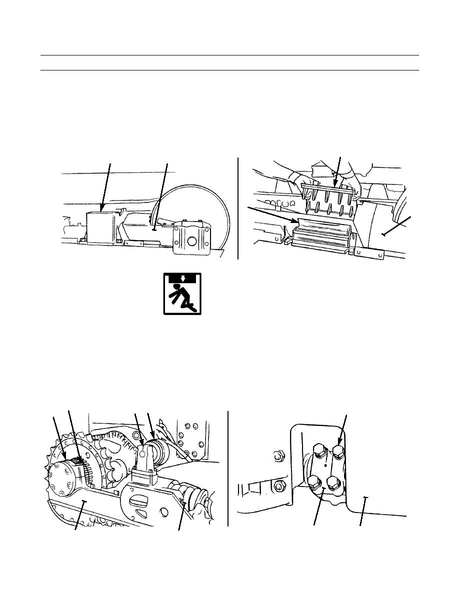
Weight of front support assembly is approximately 70 lb (32 kg).
7.
Lower front of track roller frame (1) onto track and remove front support assembly (3).
8.
Remove plate (8) and pads (9) from track roller frame (1).
8
1
3
9
1
387-684
387-685
WARNING
Ratchet puller must be attached to track roller frame in a manner to evenly distribute weight of frame.
Failure to do so may cause frame to tip, causing personal injury or death.
9.
Attach lifting device to rear track carrier roller (10) and ratchet puller to lifting device and to recoil spring (11).
10.
Adjust ratchet puller so rear track carrier roller (10), rear support assembly (3) and recoil spring (11) are level and bal-
anced.
11.
Remove four capscrews (12), lockwashers (13) and remove cap (14) from track roller frame (1). Discard lockwashers.
12.
Remove four capscrews (15), lockwashers (16) and remove cap (17) from rear of track roller frame (1). Discard lock-
washers.
12,13
3
10
15,16
14
387-687
1
17
387-686
11
1
0135 00-3
|
|
Privacy Statement - Press Release - Copyright Information. - Contact Us |
