 |
|||
|
|
|||
|
|
|||
| ||||||||||
|
|
 TM 5-2410-237-23
GOVERNOR AND FUEL INJECTION PUMP HOUSING REPLACEMENT - CONTINUED
0055 00
REMOVAL
1.
Remove crankcase breather from valve cover to access rocker arms (WP 0015 00).
2.
Perform steps 1-4 of WP 0018 00 to find top dead center (TDC) compression stroke for no. 1 piston.
3.
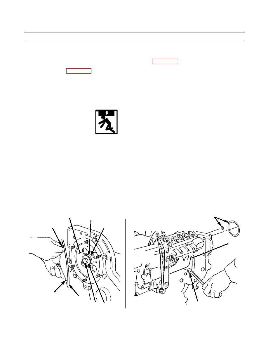
Remove six nuts (1), washers (2), pump drive gear cover (3) and gasket (4). Discard gasket.
4.
Remove capscrew (5), washer (6) and snap ring (7) from fuel injection pump camshaft (8).
5.
Attach a gear puller and remove drive gear (9) from taper on fuel injection pump camshaft (8).
WARNING
Use extreme caution when handling heavy parts. Provide adequate support and use assistance during pro-
cedure. Ensure that any lifting device used is in good condition and of suitable load capacity. Keep clear of
heavy parts supported only by lifting device. Failure to follow this warning may result in death or injury to
personnel.
NOTE
Weight of governor and fuel injection pump housing is approximately 56 lb (25 kg).
6.
Fasten a nylon sling and suitable lifting device to governor and fuel injection pump housing (10).
7.
Remove three nuts (11) and separate governor and fuel injection pump housing (10) from engine.
8.
Remove two O-rings (12) from governor and fuel injection pump housing (10). Discard O-rings.
9
12
7
1,2
8 (HIDDEN)
10
3
4
387-749
11
5
6
387-751
0055 00-2
|
|
Privacy Statement - Press Release - Copyright Information. - Contact Us |
