 |
|||
|
|
|||
|
|
|||
| ||||||||||
|
|
 TM 5-2410-237-23
CYLINDER HEAD ASSEMBLY AND SPACER PLATE REPLACEMENT - CONTINUED
0025 00
INSTALLATION - CONTINUED
9.
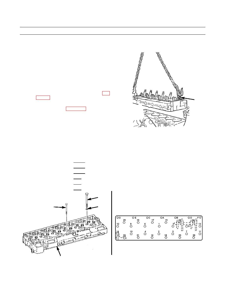
Carefully lift cylinder head and place in correct posi-
tion on cylinder block.
10.
Remove lifting device and lifting link (5).
11.
If engine is installed in vehicle:
a.
Support fan drive with lifting equipment.
b.
Remove fan drive support bracket.
c.
Install front engine lifting bracket.
d.
Install intake elbow, hose, clip and bolt (WP
5
e.
Install valve mechanism, but do not tighten cap-
screws at this time (WP 0019 00).
387-920
12.
Apply antiseize compound to threads of cylinder head capscrews.
13.
Install 20 capscrews (3), washers (4) and six capscrews (2).
14.
Tighten capscrews (2 and 3) in the following sequence:
Tighten all capscrews in number sequence to 115 lb-ft (156 Nm).
a.
Tighten all capscrews in number sequence to 185 lb-ft (251 Nm).
b.
c.
Tighten all capscrews in number sequence to 185 lb-ft (251 Nm).
Tighten all capscrews in letter sequence to 22 lb-ft (30 Nm).
d.
Tighten all capscrews in letter sequence to 32 lb-ft (43 Nm).
e.
Tighten all capscrews in letter sequence to 32 lb-ft (43 Nm).
f.
3
4
2
387-111
387-106
CYLINDER
HEAD
0025 00-6
|
|
Privacy Statement - Press Release - Copyright Information. - Contact Us |