 |
|||
|
|
|||
|
|
|||
| ||||||||||
|
|
 7-6. Recoil Springs
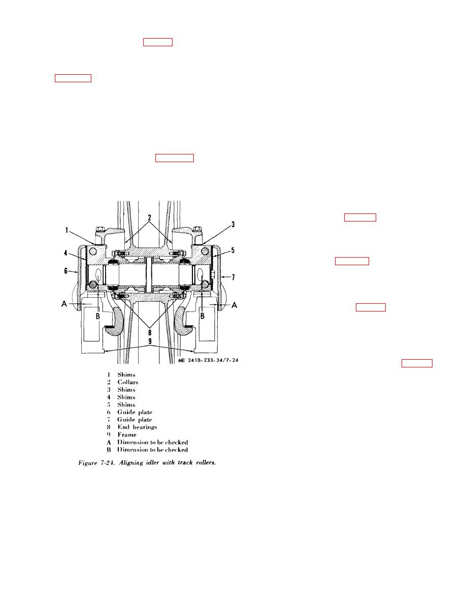
d. Front Idler Adjustment.
(1) Install shims (1, fig. 7-24) and (3) between
a. Removal.
collars (2) and bearings (8) to align the idler with
WARNING
the track rollers and keep clearance (B) between
Be certain the hydraulic pressure in the
the yoke and the plate with tolerances given in
t r a c k adjusting mechanism is com-
pletely relieved and the cylinder can be
NOTE
r e m o v e d to the rear into the recoil
Removing shims (1) or (3) from one end bearing will
spring front pilot before attempting to
tilt the top of the idler away from that bearing. Adding
separate the track or remove the track
shims to one end bearing will tilt the top of the idler
adjusting mechanism. On machines that
toward that end bearing.
have badly worn track, it is possible for
(2) Install enough shims (4) and (5) between
the hydraulic track adjuster to be ad-
bearings (8) and guide plates (6) and (7) to provide
justed forward to the limit of its travel
clearance (A) between guide plates (6) and (7) and
and t h e stop w i l l b e a g a i n s t the
the frame (9). Refer to table 1-5 for correct
equalizer bar support. The hydraulic
clearance.
cylinder could have high oil pressure in
(3) Shims (4) and (5) are used to shift tbe idler
it even though the track is loose enough
from side to side to align idler and track properly.
to remove the master pin without
relieving the hydraulic track adjusting
pressure.
(1) Remove guards (fig. 7-25). Install drawbar
pin or hardwood block between tbe sprocket and
the track, and back up the machine slightly to
com press the recoil spring. When all the tension is
rem oved from recoil spring stops, remove locking
bolt and washer (4, fig. 7-26) and screw recoil
spring bolt nut (1) tight against rear pilot (2).
Remove the drawbar pin or hardwood block.
(2) Separate the track and lay it out flat (par 7-
1).
(3) Move cylinder (5, fig. 7-27) to the rear as
far as possible, into front pilot (2), separating tbe
cylinder from idler recoil rod ( 4). Move the idler
rod to the front as far as possible.
(4) Attach a hoist to and remove the recoil
spring assembly.
(5) Inspect antiextrusion ring (2, fig. 7-31)
and seal (1).
|
|
Privacy Statement - Press Release - Copyright Information. - Contact Us |
