 |
|||
|
|
|||
|
|
|||
| ||||||||||
|
|
 (2) Inspect the idler sleeve bearings for pitting,
Be careful not to damage the metal floating ring
roughness and wear. The specified shaft to bearing
seals as they are removed.
clearance is 0.008-0.012 inch. The maximum
(4) Tape each pair of seals together to prevent
allowable shaft to bearing clearance is 0.050 inch.
intermixing them with other seals.
The specified shaft and clearance is 0.011-0.029
NOTE
inch. Replace pitted, rough, or excessively worn
When installing bearings (1) and (4), apply anti-seize
compound in bearing bores and on bearing contact
bearings.
surfaces of shaft (5).
( 3 ) Inspect the idler shaft for pitting,
roughness, and wear. Replace a damaged, ex-
(5) Remove collars (3) from both sides of idler.
cessively worn, or bent idler shaft.
(4) Inspect the metal floating ring seals for
damage and proper wear pattern. Replace seals
which are pitted, grooved, scratched across the seal
surface, or which show an uneven wear pattern.
Seals must be replaced in sets.
(5) Replace all toris sealing rings. Do not reuse
toric seal rings.
(6) Inspect bearings, guides, and collars for
cracks, breaks, or other damage. Repair by welding
and grinding smooth or replace the part.
e. Reassembly.
(1) Reassemble in the reverse order of
disassembly.
(2) Install floating seals (2) using a metal seal
installer assembly. Follow procedure outlined in
NOTE
At assembly tighten the nuts on the tapered pins to the
initial torque given in table 1-2. Use a hammer and
punch to seat the tapered pins and then tighten the
nuts to the final torque value.
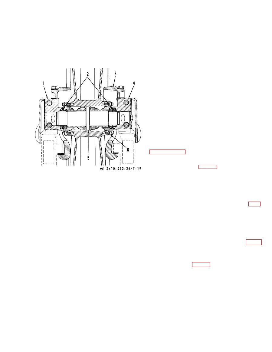
1
Bearing
2
Floating duo-cone seals
(3) Lubricate the idler.
3
Collars (2)
f. Installation.
4
Bearing
(1) Install the idler in the reverse order of
5
Shaft
rem oval.
6
Bushing assemblies (2)
(2) Align the idler with the track rollers (para
7-5).
c. Cleaning.
g. Repositioning Front Idler.
(1) Clean all parts using cleaning solvent (Fed.
NOTE
Spec. P-D-680) and dry with lint-free cloth.
The idler can be positioned from the HIGH to LOW or
(2) Remove all dirt and rust from the floating
LOW to HIGH position.
ring seal mounting grooves. Grooves must be clean,
(1) Remove the idler. Note the location of the
smooth, and dry.
recess, with the bearing in the LOW position (fig. 7-
(3) Wash protective coating from new ring
20).
seals with cleaning solvent.
(2) Rem ove the bolts, raise collars and revolve
d. Inspection and Repair.
bearings and shaft 180 so recesses are toward the
(1) Inspect the front idlers for damage and
rear of tbe machine (fig. 7-21 ). Install the bolt.
wear. When the contact surf act of the idler is worn
(3) Rotate the idler 180 in the direction
to the extent that the center flange height measure
indicated by the arrows. This will position the idler
from 1.07-1.24 inches, the idler will be repaired
properly for installation in the HIGH position. The
by welding an overlay on the wear surface. Idlers
bearing that was previously on the right side of the
worn to the extent that the center flange height
idler will now be on the left, and the recess will
measures 1.24 inches or more, will be replaced.
again be toward the front of the machine.
Idler center flange height new is 0.88 inch.
|
|
Privacy Statement - Press Release - Copyright Information. - Contact Us |
