 |
|||
|
|
|||
|
|
|||
| ||||||||||
|
|
 (2) Remove the clamping bolt and
lock
securing bearing cage holder assembly (2) to
outer
bearing adjustment nut (1).
(3) Using a puller and a step plate,
force
holder assembly (2) from taper on sprocket
shaft
(5).
NOTE
It may be necessary to strike the holder assembly with
a soft hammer to free it from taper on the shaft.
(4) Attach a hoist to support holder assembly
(2). Remove retaining nut (3), and the holder
assembly. Remove adjusting nut (1), metal floating
ring seal (9), holder assembly (2), and gasket (10),
bearing cage (7), and bearing cup (6) as a unit.
(5) Inspect the mating surfaces of metal
floating ring seals (8, and 9, fig. 6-114) for damage
or excessive wear (para 6-22).
(6) Align keyway (5) in the holder assembly
hub with the key on the sprocket shaft (6) and
install the unit in reverse order of removal.
NOTE
The bearing preload adjustment, for the hub support
bearings, is not made until the track roller frame outer
bearing has been installed. To set the bearing preload,
refer to paragraph 6-28.
b. Disassembly.
(1) Remove the dust guard.
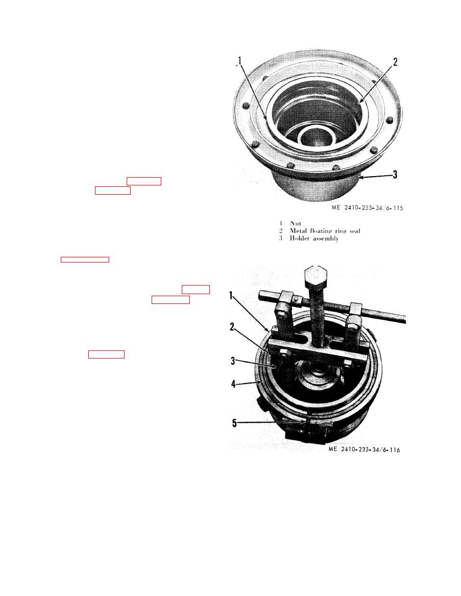
(2) Remove metal floating ring seal (2, fig. 6-
115), if replacement is necessary (para 6-22).
(3) Remove outer bearing adjusting nut (1)
from bearing cage holder assembly (3).
(4) Using a bearing cup pulling attachment, a
forcing bolt, a suitable spacer to cover the hole in
the holder assembly hub, and a step plate, pull
bearing cage (2, fig. 6-116) and cup (3) as a unit.
(5) Remove bearing cage holder gasket (4)
and seal (5) if replacement is necessary.
(6) Using a puller, an adapter and a bearing
cup pulling attachment, remove the cup (3) from
the bearing cage.
1
Holder assembly
2
Cage
3
Cup
4
Gasket
5
Seal
|
|
Privacy Statement - Press Release - Copyright Information. - Contact Us |
