 |
|||
|
|
|||
|
Page Title:
Aligning Track Roller Frame With Sprocket |
|
||
| ||||||||||
|
|
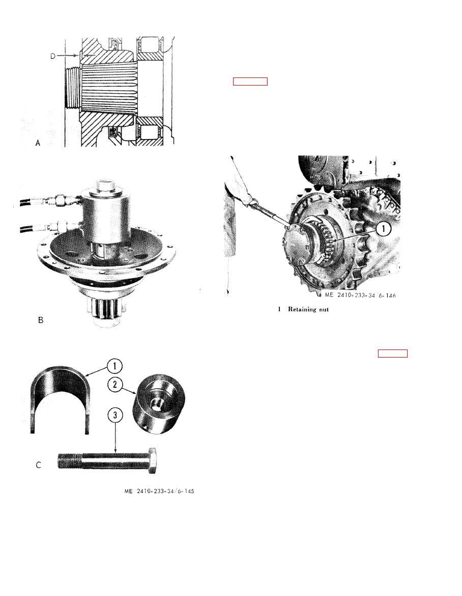 6-28. Final Drive Bearing Adjustments
a. After the final drive has been assembled and
the track roller frame outer bearing installed and
aligned, adjust the bearing preload on the sprocket
support bearings. With the adjusting nut lock and
clamping bolt removed, tighten the adjusting nut
(1, fig. 6-146) in a counterclockwise direction to the
torque value of 1200-1500 lb-ft.
b. Continue to tighten the nut until the lock can
be installed in one of the recesses in the retaining
nut.
c. Insert the clamping bolt and tighten to lock the
retaining nut in position.
6-29. Aligning T r a c k Roller Frame With
Sprocket
147) the center of the track rollers should be
centered with final drive sprocket (8), so the track
will lead straight off of rear roller (5) onto the final
drive sprocket and not rub against either the sides
of the sprocket or the rims of the track roller.
b. Final drive sprocket (8) should be centered in
the recess of rear track roller (5) so clearances (10)
and (12) between the outer face of the sprocket and
the inner edge of the track roller are equal.
c. When this properly adjusted, diagonal brace
(13) should be checked to see there is some
clearance at (14) and (15) in the recess in steering
clutch case (16).
d. To make this adjustment remove cap (1) from
outer bearing assembly (4) and remove lockring
(7), nut (2) and retainer assembly (9).
e. Add shims (3) between retainer assembly (9)
1 Sleeve
and holder assembly (11) to move the track roller
2 Adapter
3 Bolt
frame out, decreasing clearance (12) at the roller
D Dimension to be checked 0.094 in.-0.154 in.
and at diagonal brace (13) and increasing clearance
at (10) and (15).
|
|
Privacy Statement - Press Release - Copyright Information. - Contact Us |
