 |
|||
|
|
|||
|
Page Title:
Steering Clutch Hydraulic Controls |
|
||
| ||||||||||
|
|
 6-17. Steering Clutch Hydraulic Controls
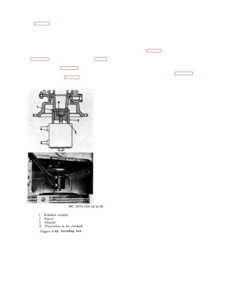
(2) Align the locating dowel in the retainer
washer (1, fig. 6-98) with the dowel hole in the hub.
a. General.
Install the washer.
(1) Filtered oil is delivered by the steering
( 3 ) Assemble bolt adapter (3) to the hydraulic
clutch hydraulic oil pump to the steering clutch
puller and install the adapter (3) on the clutch
control valve housing.
shaft.
(2) The steering clutch control levers are
(4) Place the spacer (2) over the adapter as
connected, through mechanical linkages, to levers
shown.
on the shafts (1, fig. 6-99). When the control levers
(5) Press the hub onto the shaft to the pressure
are pulled to release the steering clutches, the shafts
g i v e n in table 1-4. Measure the distance (A, fig. 6-
( 1 , and 2) are rotated causing the levers (3 and 4)
98) from the shoulder on clutch shaft to the face of
t o contact the plungers (5) and move them to the
t h e clutch hub. Refer to table 1-4 for the correct
r e a r . The plungers operate the control valves which
dimension.
direct oil to the control pistons (1, fig. 6-100) in the
(6) Install the pilot (7, fig. 6-96) lock (11), nut
steering clutch hubs. The oil behind the piston
(4), and piston (2) in reverse order of removal.
moves them toward the steering clutches, com-
p r e s s i n g the steering clutch springs (2) and moving
the pressure plate (3) out of contact with the clutch
discs.
|
|
Privacy Statement - Press Release - Copyright Information. - Contact Us |
