 |
|||
|
|
|||
|
Page Title:
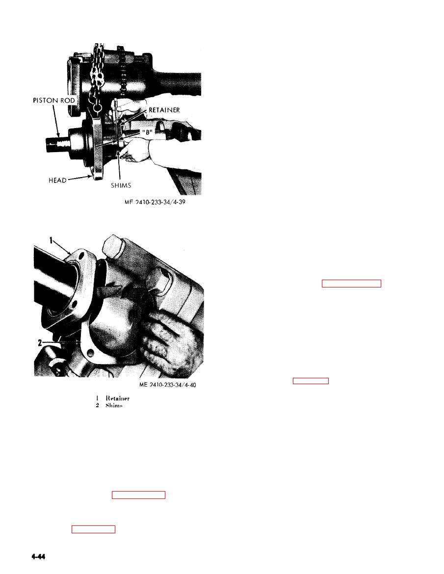
Figure 4-39. Measuring clearance. |
|
||
| ||||||||||
|
|
 CAUTION
Extend the piston rod out of the
cylinder before removing bolts, to
p r e v e n t scoring of the cylinder walls
w h e n removing the piston from the
cylinder.
d. Cleaning. Clean all parts with cleaning
solvent (Fed. Spec. P-D-680). Dry parts with a lint-
free cloth.
e. Inspection and Repair.
(1) Inspect the cylinder for scoring, pitting,
and wear. Replace a cylinder which cannot be
made serviceable with light honing.
CAUTION
Do not weld on the cylinder assembly as
scoring may result from shrinkage.
(2) Replace all seals, packing, and wear rings.
(3) Inspect the rod end bearing for scoring,
damage, and wear.
(4) Inspect the piston rod for nicks, burrs,
pitting, distortion, and wear. Repair or replace a
damaged or distorted rod. Remove minor nicks and
burrs using a fine emery stone. Pitted, scored, or
worn rods may be repaired by metalizing or
chrome-plating and regrinding to original size. A
noncorrosive metal will be used to metalize shafts.
(5) Inspect remaining cylinder parts for wear
or damage. Replace all defective parts.
install the ripper "lift" cylinders on the ripper.
Key to figure 4-41.
1 Bearing
2 Rod
3 Seal
4 Bolt
5 Lockwasher
6 Retainer
h. Installation. Reverse removal procedure and
7 Shim
install the tilt cylinder on the bulldozer.
8 Shim
9 Packing
10 Screw
a. General. The ripper hydraulic lift cylinders
11 Lockwasher
are located on each side of the ripper and are used
12 Head
13 Packing
to raise and lower the ripper. Both cylinders are
14 Washer
removed and installed in a similar manner.
15 Seal assembly
16 Piston
the cylinders.
17 Ring
c. Disassembly. Disassemble t h e ripper lift
18 Nut
19 Fitting
cylinders according to sequence of index numbers
20 Cylinder assembly
assigned to figure 4-41.
|
|
Privacy Statement - Press Release - Copyright Information. - Contact Us |