 |
|||
|
|
|||
|
|
|||
| ||||||||||
|
|
 f. Cleaning. Clean all parts with cleaning solvent
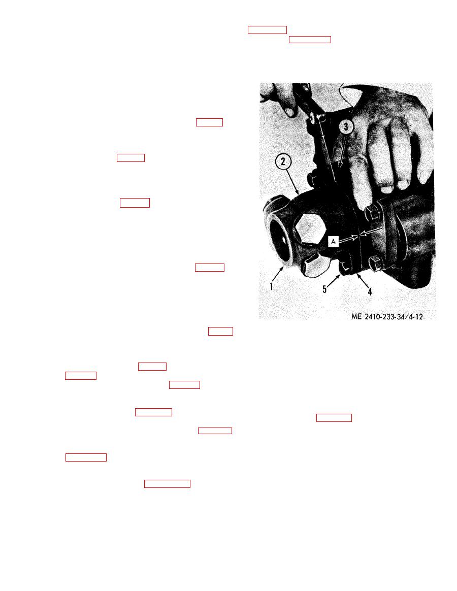
spacer (3), figure 4-12, tight against the valve body
(Fed. Spec. P-D-680) and dry with clean com-
and measure clearance (A) between housing (2)
pressed air or wipe dry using a lint-free cloth.
g. Inspection and Repair.
and spacer (3) with a thickness gage. Install shims
(4) with a thickness equal to this measurement.
(1) Inspect valve body and spool for nicks,
burrs, pitting, and wear. Light scratches or a light
grey wear appearance are not harmful to the valve.
Examine the valve land edges for wear. If wear or
damage exists, the complete valve assembly must
be replaced.
(2) Inspect detent plug assemblies (2, fig. 4-5)
for weak or damaged springs and worn or damaged
balls. Replace as required.
(3) Inspect the check valve for weak or
damaged spring (4, fig. 4-7) and free movement of
valve in bore. Inspect valve chamfered seating
surface and valve seat in body (7), for nicks, burrs
and proper contact. Replace as required.
(4) Inspect the make-up valves for weak or
damaged springs (3, fig. 4-9) and free movement of
valve (4) in bores. Inspect valve chamfered seating
surfaces and valve seats in body (5) for nicks,
burrs, and 100 percent contact. Finger pressure
against the face of the valve should open it and the
spring should return the valve to closed position.
Replace defective springs or valves.
(5) Inspect control shaft bearings (6, fig. 4-11)
for corrosion, roughness, and wear. Replace
corroded, rough, or worn bearings.
(6) Replace control shaft oil seal (7). Examine
control shaft for wear due to seal contact. Replace
shaft if deeply grooved.
h. Reassembly.
(1) Reassemble the control lever using figure
1
Spool
4-11 as a guide. Install the seal (7), with the lip
2
Housing
3
Spacer
toward bearings (6) and the metal case flush with
4
Shims
the outside face of the housing (5). Position and
5
Bolts (2)
install the outer lever (4, fig. 4-10) on control lever
A
Clearance to be measured
(3, fig. 4-11) until it is snug but not tight against
washer (1), then tighten bolt (3, fig. 4-10). Check
for binding.
i. Installation. Reverse removal procedure,
(2) Reassemble make-up valves and springs.
install bulldozer control valve and torque bolts (3),
Torque bolts (1) and (6), Figure 4-8, to 60 2 ft-
(7), (8) and (12), figure 4-4, to 60 2 ft-lbs.
lbs. Torque bolts (4) to 60 2 ft-lbs.
(3) Reassemble the check valve using figure 4-
7 as a guide. Install valve in housing.
a. General. The bulldozer relief valve ((1), fig. 4-
(4) Reassemble and install the control valve
13) mounted on the bottom plate of the hydraulic
using figures 4-5 and 4-6 as guides. To obtain the
tank, prevents excessive pressures from being
correct thickness of shims required, assemble and
imposed on the large section of the two-section
install the valve spool. Install housing without
pump and other components of the bulldozer
shims. Tighten bolts (5), figure 4-12, until the
circuit.
shoulder in the housing just contacts retainer (2),
|
|
Privacy Statement - Press Release - Copyright Information. - Contact Us |