 |
|||
|
|
|||
|
Page Title:
Figure 2-20. Three seal cylinder head. |
|
||
| ||||||||||
|
|
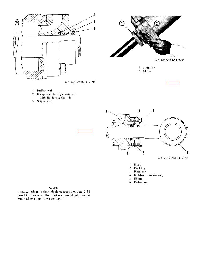 (a) Place retainer (3, fig. 2-22) on rod
(6). Separate and oil all the rings of packing (2).
Place the packing on the rod so the open part of the
V will be facing toward head (1) when the head is
installed. Be sure rubber pressure ring (4) is located
as shown.
(e) Cylinder head packing adjustment.
1. Oil leakage between the rod and the
hydraulic cylinder packing can be the result of
w o r n , cut, and/or distorted packing. Leakage can
o f t e n be stopped by removing shims (2, fig. 2-21)
located between retainer (1) and the cylinder head;
this will allow the packing to be compressed against
t h e rod when the retainer is tightened.
2 . Remove the bolts securing retainer to
the cylinder head. Move the retainer away from the
cylinder head to allow the shims to be cut and
removed.
3 . Remove one shim (2); install retainer
(1) and operate the cylinder. If leakage is still
apparent, repeat the procedure. If the cylinder
leaks after removing two shims, remove and
d i s a s s e m b l e the cylinder and replace the packing.
|
|
Privacy Statement - Press Release - Copyright Information. - Contact Us |
