 |
|||
|
|
|||
|
Page Title:
Figure 2-16. Shear-type fitting. |
|
||
| ||||||||||
|
|
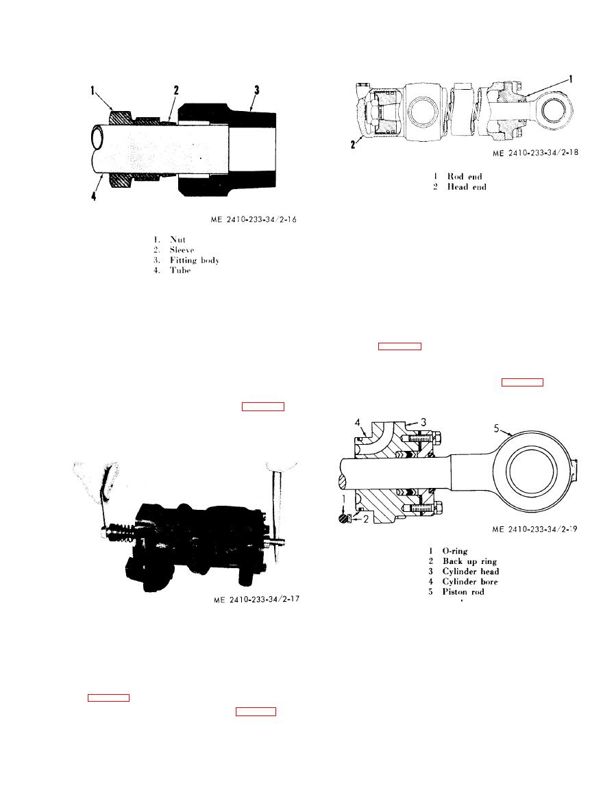 retract the rod. The head end line directs oil to the
nut. Tighten the nut an additional 1 turns. It is
head end of the cylinder to extend the rod.
not necessary to tighten the nut all the way down.
(b) Removal. The hydraulic system need not
be drained to remove any or all cylinders. Only the
oil in the lines between the cylinder and its control
v a l v e will be lost. However, the control lever must
remain in HOLD position or oil can drain from the
t a n k in some instances.
(c) Disassembly and assembly. R e m o v e a n d
(6)
Hydraulic
valves.
i n s t a l l the bolts securing the cylinder head to the
(a) E x a m i n e a l l v a l v e s , v a l v e b o r e s a n d
c y l i n d e r with the piston rod fully extended.
valve
seats for nicks, burrs and/or scratches.
(d) Cylinder head seals. T h e r u b b e r O - r i n g
( R o u g h spots may be removed with a crocus cloth
s e a l (1, fig. 2-19) and the backup ring (2) which
form the seal between the head (3) and cylinder
o r fine emery cloth). All valves which operate in
bores must slide freely in their bores. Be certain all
bore (4) are all assembled as illustrated. Note that
the toe or lip of all wiper seals (3, fig. 2-20) on all
p a s s a g e s are clean and open.
cylinders faces away from the cylinder head.
(b) O n c o n t r o l v a l v e s p o o l s h a v i n g b o l t -
r e t a i n e d centering or return springs (fig. 2-17) the
b o l t S hould be removed while the valve spool is in
t h e valve body. This procedure will prevent spool
d i s t o r t i o n and possible damage to the spool lands.
(c) When installing shims to adjust pressure
settings, a l w a y s p l a c e t h e t h i c k s h i m o r s p a c e r
against the spring.
(7) Cylinders.
( a ) Rod end and head end. T h e " r o d e n d "
(1, fig. 2-18) of a cylinder is that end that has the
r o d extending. The "head end" (2, fig. 2-18) is the
o t h e r end of the cylinder-the blind end. The rod
end line directs oil to the rod end of the cylinder to
|
|
Privacy Statement - Press Release - Copyright Information. - Contact Us |
