 |
|||
|
|
|||
|
|
|||
| ||||||||||
|
|
 TM 5-2410-233-23
RIPPER LIFT CYLINDER REPAIR - CONTINUED
0164 00
DISASSEMBLY
NOTE
Prior to disassembly of lift cylinder, inspect external casing of lift cylinder for serviceability (cracks and
damage). If not serviceable, replace lift cylinder.
1.
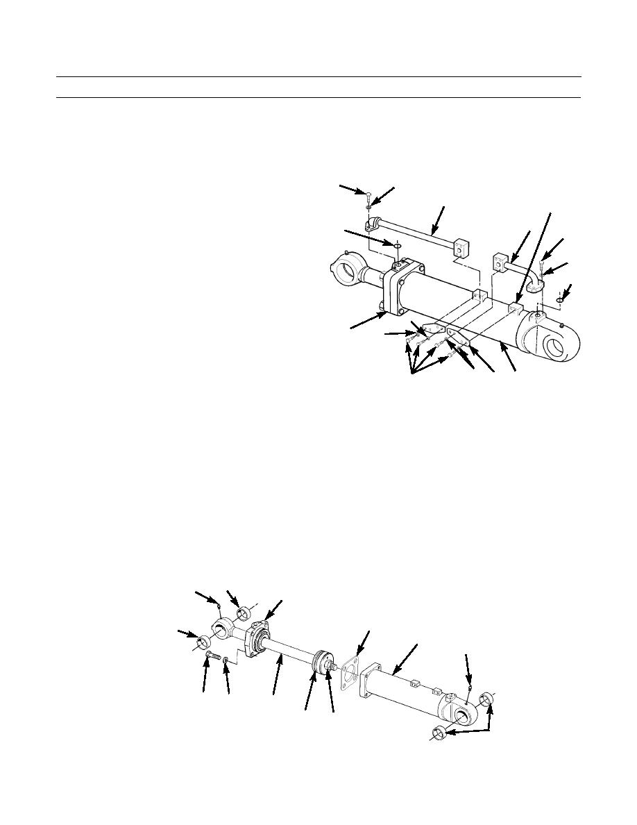
Scribe a mark on head (1) and cylinder housing (2) for
7
8
correct alignment at assembly.
9
6
2.
Remove eight capscrews (3) and washers (4) holding
two plates (5) to bosses (6) on cylinder housing (2).
9
10
7
3.
Remove six capscrews (7), washers (8), two tube
assemblies (9) and O-rings (10) from head (1) and cyl-
8
inder housing (2). Discard O-rings.
10
4
1
4
386-570
4
2
5
3
4.
Remove four capscrews (11) and washers (12) from head (1).
5.
Pull piston rod (13) and piston assembly slowly from cylinder housing (2) to allow oil to escape.
6.
Remove shim pack (14) from head (1). Discard shim pack if found worn or damaged.
7.
If required, remove two grease fittings (15) from cylinder housing (2) and piston rod (13).
8.
Inspect four bearing sleeves (16) for serviceability. Replace lift cylinder if not serviceable.
CAUTION
Protect piston rod and use care when placing in vise.
9.
Place piston rod (13) in vise and remove self-locking nut (17) from piston rod. Discard self-locking nut.
10.
Remove piston (18) from piston rod (13).
16
15
1
14
16
2
15
11
12
13
18
17
16
386-571
0164 00-2
|
|
Privacy Statement - Press Release - Copyright Information. - Contact Us |