 |
|||
|
|
|||
|
|
|||
| ||||||||||
|
|
 TM 5-2410-233-23
BLADE CONTROL LEVER AND LINKAGES REPLACEMENT - CONTINUED
0152 00
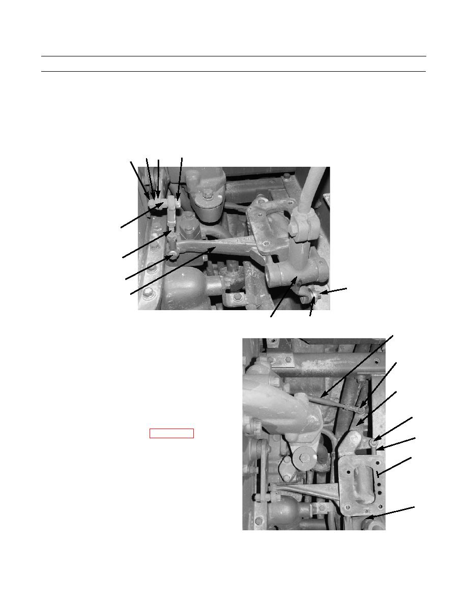
REMOVAL
1.
Remove nut (1), lockwasher (2), nut (3) and bolt (4) from tilt control lever (5) and tilt control linkage (6). Discard lock-
washer.
2.
Remove nut (7) and bolt (8) from tilt control linkage (6) and bell crank (9). Remove tilt control linkage.
3.
Remove bolt (10) from linkage (11) and control lever (12).
2
4
5
1
3
6
7,8
10
9
386-770
11
12
4.
Remove bolt (13) from linkage (11) and bell crank
16
(14). Remove linkage from control lever (12) and bell
crank.
15
5.
Remove bolt (15) from linkage (16) and bell crank
(14). Remove linkage from bell crank.
14
NOTE
Linkage is connected to main (bulldozer) con-
trol valve lever under hydraulic tank.
13
6.
If removal of linkage (16) is necessary, refer to
11
7.
Remove linkage bracket assembly (17) from machine.
17
12
386-771
0152 00-2
|
|
Privacy Statement - Press Release - Copyright Information. - Contact Us |
