 |
|||
|
|
|||
|
Page Title:
RELIEF VALVE SETTING ADJUSTMENT |
|
||
| ||||||||||
|
|
 TM 5-2410-233-23
MAIN (BULLDOZER) CONTROL VALVE, RIPPER CONTROL VALVE
AND RELIEF VALVE REPLACEMENT - CONTINUED
0151 00
RELIEF VALVE SETTING ADJUSTMENT
NOTE
Adjustment can be performed without removing valve.
1.
Remove floor plates (WP 0135 00).
CAUTION
To prevent contamination of hydraulic system, keep work area clean.
2.
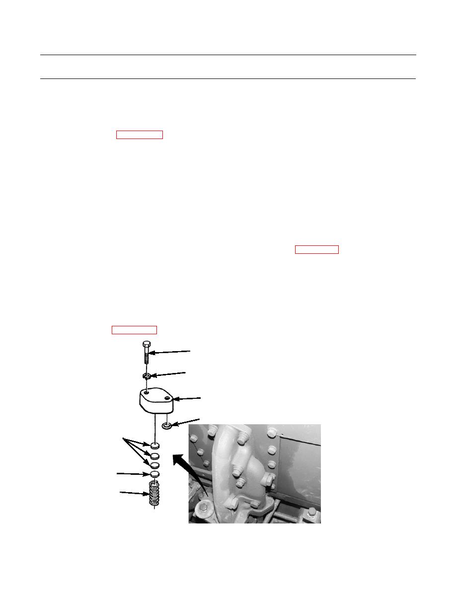
Remove two bolts (52), lockwashers (53), and cover (54) from valve body. Discard lockwashers.
3.
Remove two O-rings (55) from cover (54). Discard O-rings.
4.
Remove three disks (56) and shims (57) from spring (58).
NOTE
Adding one shim increases pressure by 35 psi (241.3 kPa). Removing one shim decreases pressure by the
same valve.
5.
Determine number of shims (57) needed to achieve proper relieve valve setting (WP 0167 00).
6.
Install correct number of shims (57) and three disks (56) on spring (58).
NOTE
Lightly coat new O-rings with clean oil before installation.
7.
Install two new O-rings (55) in cover (54).
8.
Install cover (54) with two new lockwashers (53) and bolts (52).
9.
Install floor plates (WP 0135 00).
52
53
54
55
56
57
58
386-824
END OF WORK PACKAGE
0151 00-13
|
|
Privacy Statement - Press Release - Copyright Information. - Contact Us |
