 |
|||
|
|
|||
|
Page Title:
RIPPER CONTROL VALVE REMOVAL - CONTINUED |
|
||
| ||||||||||
|
|
 TM 5-2410-233-23
MAIN (BULLDOZER) CONTROL VALVE, RIPPER CONTROL VALVE
AND RELIEF VALVE REPLACEMENT - CONTINUED
0151 00
RIPPER CONTROL VALVE INSTALLATION -
29
25,26,27
28
31
CONTINUED
(HIDDEN)
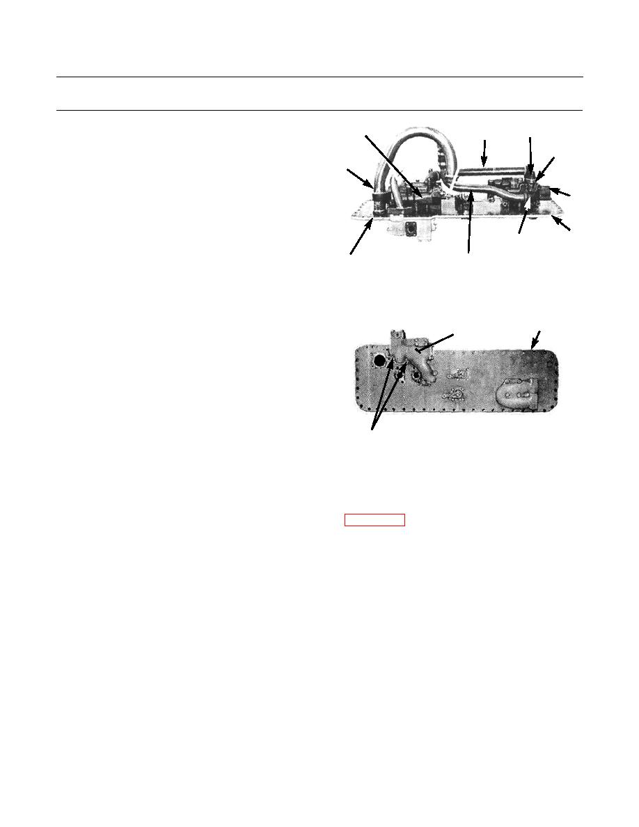
5.
Install two new lockwashers (35) and bolts (34) to end
23
cap (36) of ripper control valve oil return line (37).
6.
Position two new gaskets (31) and each end cap (27)
30
of oil line (28) between main (bulldozer) control valve
(29) and ripper control valve (30). Install four new
lockwashers (26) and bolts (25).
8
34,35,36
386-738
21,22,24
37
7.
Perform steps 8 through 18 of Main (Bulldozer) Control Valve Installation.
RELIEF VALVE REMOVAL
8
49
1.
Perform steps 1 through 5 of Main (Bulldozer) Control
Valve Removal to access relief valve (49) on bottom
plate (8).
2.
Remove four bolts (50), lockwashers (51) and relief
valve (49) from bottom plate (8). Discard
lockwashers.
386-739
50,51
RELIEF VALVE INSTALLATION
NOTE
Apply sealing compound to relief valve mounting bolts before installation.
1.
Position relief valve (49) on bottom plate (8) and install four new lockwashers (51) and bolts (50).
2.
Perform steps 8 through 18 of Main (Bulldozer) Control Valve Installation.
0151 00-12
|
|
Privacy Statement - Press Release - Copyright Information. - Contact Us |
