 |
|||
|
|
|||
|
Page Title:
MAIN (BULLDOZER) CONTROL VALVE INSTALLATION - CONTINUED |
|
||
| ||||||||||
|
|
 TM 5-2410-233-23
MAIN (BULLDOZER) CONTROL VALVE, RIPPER CONTROL VALVE
AND RELIEF VALVE REPLACEMENT - CONTINUED
0151 00
MAIN (BULLDOZER) CONTROL VALVE INSTALLATION - CONTINUED
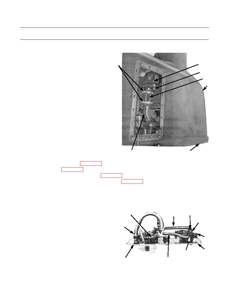
12.
Position extension tube (5) at pump suction tube (6)
and install two washers (4) and bolts (3).
5
1
13.
Tighten two hose clamps (1) on hose (2).
3,4
2
7
386-755
8
6
14.
Install hydraulic tilt control valve (WP 0150 00).
15.
Install hydraulic tank (WP 0166 00).
16.
Refill hydraulic tank and bleed air from system (WP 0165 00).
17.
Perform hydraulic system pressure tests and adjust as needed (WP 0167 00).
18.
Operate machine and check for leaks and proper operation (TM 5-2410-233-10).
RIPPER CONTROL VALVE REMOVAL
1.
Perform steps 1 through 5 of Main (Bulldozer) Control Valve Removal to access ripper control valve (30) on bottom
plate (8)
2.
Remove four bolts (25) and lockwashers (26) from
29
25,26,27
28
end caps (27) of oil line (28) between main (bulldozer)
31
(HIDDEN)
control valve (29) and ripper control valve (30). Dis-
23
card lockwashers.
3.
Remove oil line (28) with end caps (27) and gaskets
(31). Discard gaskets.
30
4.
Remove two bolts (34) and lockwashers (35) from end
cap (36) of ripper control valve oil return line (37).
8
Discard lockwashers.
34,35,36
386-738
21,22,24
37
0151 00-8
|
|
Privacy Statement - Press Release - Copyright Information. - Contact Us |
