 |
|||
|
|
|||
|
Page Title:
MAIN (BULLDOZER) CONTROL VALVE INSTALLATION - CONTINUED |
|
||
| ||||||||||
|
|
 TM 5-2410-233-23
MAIN (BULLDOZER) CONTROL VALVE, RIPPER CONTROL VALVE
AND RELIEF VALVE REPLACEMENT - CONTINUED
0151 00
MAIN (BULLDOZER) CONTROL VALVE INSTALLATION - CONTINUED
8.
Install lifting link with 1/2-13 x 1 in. bolt to center threaded hole on top of hydraulic tank (7).
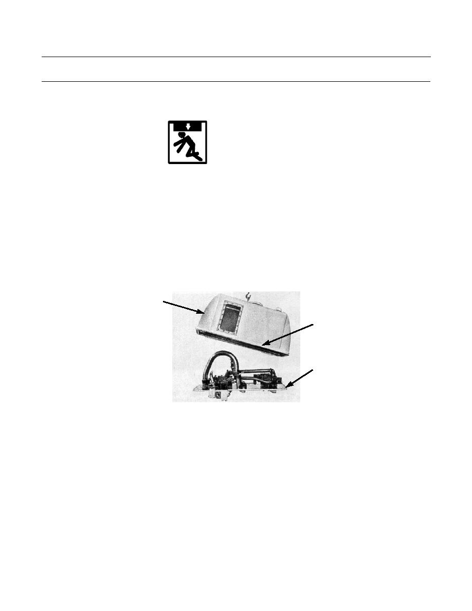
WARNING
Use extreme caution when handling heavy parts. Provide adequate support and use assistance during pro-
cedure. Ensure that any lifting device used is in good condition and of suitable load capacity. Keep clear of
heavy parts supported only by lifting device. Failure to follow this warning may result in injury or death to
personnel.
NOTE
Hydraulic tank weighs approximately 226 lb (103 kg).
9.
Attach a nylon sling and suitable lifting device to lifting link.
10.
Lift hydraulic tank (7) into position over bottom plate (8), with bolt holes aligned.
11.
Install 20 new lockwashers (10) and bolts (9) to hydraulic tank (7) and bottom plate (8).
7
9,10
8
386-756
0151 00-7
|
|
Privacy Statement - Press Release - Copyright Information. - Contact Us |
