 |
|||
|
|
|||
|
Page Title:
MAIN (BULLDOZER) CONTROL VALVE INSTALLATION - CONTINUED |
|
||
| ||||||||||
|
|
 TM 5-2410-233-23
MAIN (BULLDOZER) CONTROL VALVE, RIPPER CONTROL VALVE
AND RELIEF VALVE REPLACEMENT - CONTINUED
0151 00
MAIN (BULLDOZER) CONTROL VALVE INSTALLATION - CONTINUED
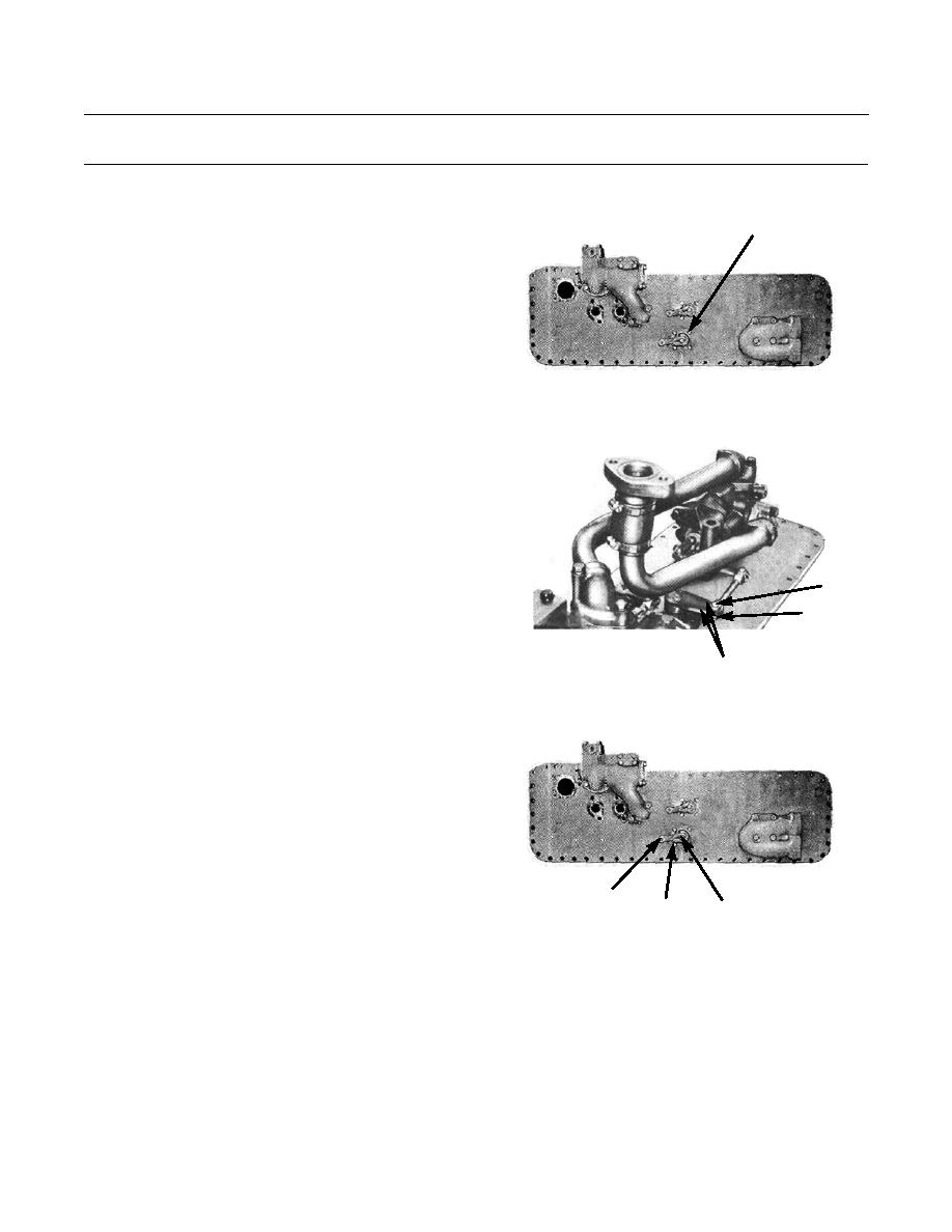
5.
Position lever group (20) on bottom plate (8). Secure
18,19,20
with four new lockwashers (19) and bolts (18).
386-739
6.
Position links (17) to top of shaft (14). Install pin (16)
and retaining clip (15) to links.
16
15
386-742
17
7.
Install main (bulldozer) control valve lever (12) and
key (13) on shaft (14). Tighten bolt (11).
386-739
12,13
11
14
0151 00-6
|
|
Privacy Statement - Press Release - Copyright Information. - Contact Us |
