 |
|||
|
|
|||
|
Page Title:
MAIN (BULLDOZER) CONTROL VALVE REMOVAL |
|
||
| ||||||||||
|
|
 TM 5-2410-233-23
MAIN (BULLDOZER) CONTROL VALVE, RIPPER CONTROL VALVE
AND RELIEF VALVE REPLACEMENT - CONTINUED
0151 00
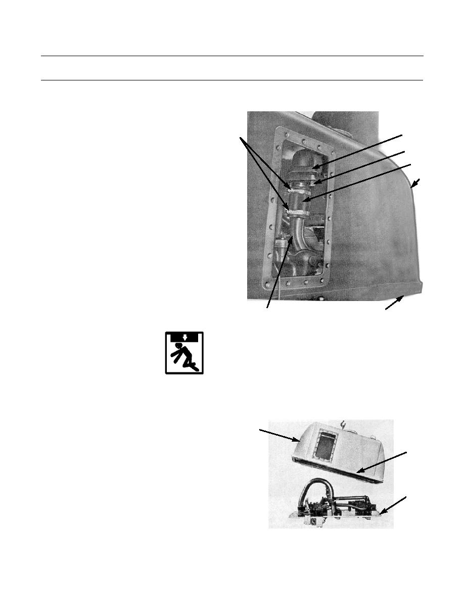
MAIN (BULLDOZER) CONTROL VALVE REMOVAL
NOTE
Use a suitable container to capture residual
5
1
draining oil. Dispose of oil IAW local policy and
ordinances. Ensure all spills are cleaned up.
3,4
1.
Loosen two hose clamps (1) on hose (2).
2
2.
Remove two bolts (3) and washers (4) securing exten-
7
sion tube (5) to pump suction tube (6). Rotate exten-
sion tube within hydraulic tank (7) so it will not
interfere with removal of tank from bottom plate (8).
3.
Install lifting link with 1/2-13 x 1 in. bolt in center
threaded hole on top of hydraulic tank (7).
386-755
8
6
WARNING
Use extreme caution when handling heavy parts. Provide adequate support and use assistance during pro-
cedure. Ensure that any lifting device used is in good condition and of suitable load capacity. Keep clear of
heavy parts supported only by lifting device. Failure to follow this warning may result in injury or death to
personnel.
NOTE
7
Hydraulic tank weighs approximately 226 lb
(103 kg).
9,10
4.
Attach a nylon sling and suitable lifting device to lift-
ing link on hydraulic tank (7).
5.
Remove 20 bolts (9) and lockwashers (10) and lift
hydraulic tank (7) from bottom plate (8). Discard lock-
8
washers.
386-756
0151 00-2
|
|
Privacy Statement - Press Release - Copyright Information. - Contact Us |
