 |
|||
|
|
|||
|
Page Title:
MAIN (BULLDOZER) CONTROL VALVE REMOVAL - CONTINUED |
|
||
| ||||||||||
|
|
 TM 5-2410-233-23
MAIN (BULLDOZER) CONTROL VALVE, RIPPER CONTROL VALVE
AND RELIEF VALVE REPLACEMENT - CONTINUED
0151 00
MAIN (BULLDOZER) CONTROL VALVE REMOVAL - CONTINUED
6.
Loosen bolt (11) and remove main (bulldozer) control
valve lever (12) and key (13) from shaft (14).
386-739
12,13
11
14
NOTE
Main (bulldozer) control valve and ripper control valve internal linkages are disconnected
and removed in the same manner.
Ripper control valve linkage is shown because it can be clearly shown in art.
7.
Remove retaining clip (15) and pin (16) from links
(17).
8.
Separate links (17) from top of shaft (14).
16
15
386-742
17
9.
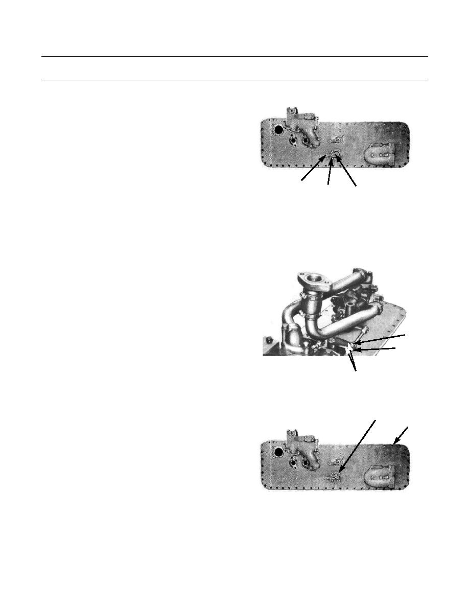
Remove four bolts (18) and lockwashers (19) securing
18,19,20
lever group (20) to bottom plate (8). Remove lever
8
group and discard lockwashers.
386-739
0151 00-3
|
|
Privacy Statement - Press Release - Copyright Information. - Contact Us |