 |
|||
|
|
|||
|
|
|||
| ||||||||||
|
|
 TM 5-2410-233-23
WINCH ASSEMBLY REPLACEMENT - CONTINUED
0139 00
INSTALLATION - CONTINUED
WARNING
Use extreme caution when handling heavy parts. Provide adequate support and use assistance during pro-
cedure. Ensure that any lifting device used is in good condition and of suitable load capacity. Keep clear of
heavy parts supported only by lifting device. Failure to follow this warning may cause injury or death.
NOTE
Use a tap to chase and clean threaded holes in bosses to which chain end links are attached.
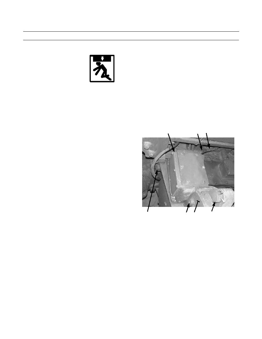
4.
Attach two lifting links with 3/4 -10 x 1-1/2 in. bolts in
6
5
7
threaded boss (8) on each side of winch (9).
5.
Attach a suitable three-point lifting device to two lift-
ing links on each side of winch (9) and to bar (10).
CAUTION
Use caution when aligning drive shaft to drive
shaft opening at rear of tractor. Install winch
slowly and carefully. Failure to maintain con-
trol of winch while it is inserted could cause
damage to mounting studs, drive shaft and
transmission.
NOTE
Assistance is required to align winch
drive shaft with transmission cou-
386-046
pling and output shaft.
11,12,13,14
10
8
9
Adjust lifting device as needed until
correct alignment is achieved.
6.
Align winch drive shaft (14) with opening in back of tractor. Rotate winch drive shaft to ensure that splines of transmis-
sion coupling and output shaft line up.
NOTE
Winch is correctly aligned and installed when winch case is flush against rear of tractor.
7.
Slowly move winch (9) toward tractor until coupling (20) on drive shaft (14) is seated in transmission and winch is
mounted on studs (13).
8.
Install six washers (12) and nuts (11) on studs (13).
9.
Tighten four nuts (11) at four larger mounting studs to 1500 lb-ft (2034 Nm).
10.
Tighten two nuts (11) at two smaller studs (13) to 1000 lb-ft (1356 Nm).
11.
Remove lifting device and two lifting links from threaded boss (8) on each side of winch (9).
12.
Connect coupling (5) of winch pump pressure line (6) to valve housing (7).
0139 00-5
|
|
Privacy Statement - Press Release - Copyright Information. - Contact Us |
