 |
|||
|
|
|||
|
|
|||
| ||||||||||
|
|
 TM 5-2410-233-23
WINCH ASSEMBLY REPLACEMENT - CONTINUED
0139 00
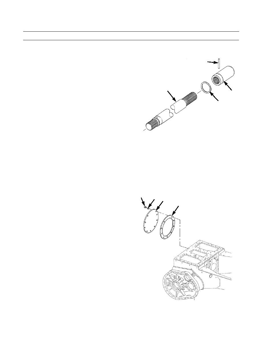
REMOVAL - CONTINUED
13.
Remove pin (19), coupling (20) and retaining ring (21)
19
from transmission end of winch drive shaft (14).
14
20
21
386-047
INSTALLATION
NOTE
Winch assembly weighs approximately 3,600 lb (1,634 kg).
Prior to installation, ensure all traces of paint or rust have been removed from mounting sur-
faces of winch and tractor and from mounting studs.
Wipe clean all retaining rings and grooves in components.
1.
Lightly lubricate, then temporarily position retaining
18
17
16
ring (21) on groove end of coupling (20). Do NOT
15
install retaining ring in groove at this time.
2.
Install coupling (20) on winch drive shaft (14), align
holes and install pin (19). Retain pin by sliding retain-
ing ring (21) into groove in coupling.
NOTE
If cover is installed, perform Step 3.
3.
Remove nine capscrews (18), lockwashers (17), round
cover (16) and gasket (15) from drive shaft opening in
final drive case at rear of tractor. Discard lockwashers
and gasket.
386-048
0139 00-4
|
|
Privacy Statement - Press Release - Copyright Information. - Contact Us |
