 |
|||
|
|
|||
|
|
|||
| ||||||||||
|
|
 TM 5-2410-233-23
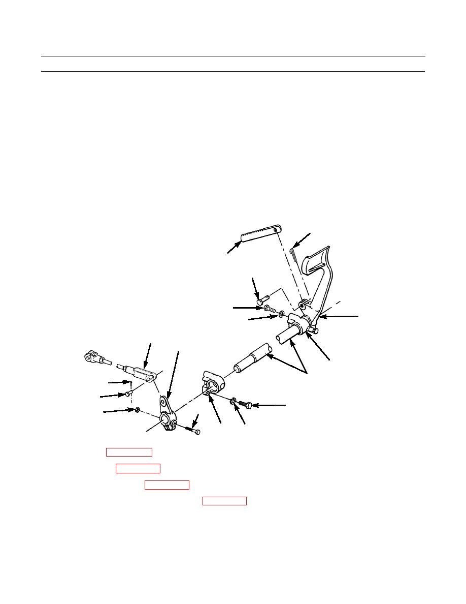
STEERING BRAKE PEDALS AND LINKAGE MAINTENANCE - CONTINUED
0121 00
INSTALLATION - CONTINUED
10.
Install lever (8) on end of shaft (12).
11.
Install bolt (14) and nut (13) in lever (8) to secure lever to shaft (12).
12.
Install two bellcranks (11) and R.H foot pedal (4) on shaft (12) and install as an assembly on crossbeam under floor
using four bolts (9) and new lockwashers (10).
13.
Install rod end (7) on lever (8) with pin (6) and new cotter pin (5).
14.
Install ratchet (3) on R. H. foot pedal (4) with pin (2) and new cotter pin (1).
15.
Repeat step 14 for L H. foot pedal.
1
3
2
9
4
10
7
8
11
12
5
6
R.H. PEDAL AND
9
14
13
LINKAGE ASSEMBLY
11
10
386-630
16.
Adjust linkages (WP 0126 00).
17.
Install floor plates (WP 0135 00).
18.
If removed, install fuel tank (WP 0049 00).
19.
If removed, install seat and seat base assembly (WP 0137 00).
20.
Test drive and check for proper operation (TM 5-2410-233-10).
END OF WORK PACKAGE
0121 00-6
|
|
Privacy Statement - Press Release - Copyright Information. - Contact Us |
