 |
|||
|
|
|||
|
|
|||
| ||||||||||
|
|
 TM 5-2410-233-23
STEERING BRAKE PEDALS AND LINKAGE MAINTENANCE - CONTINUED
0121 00
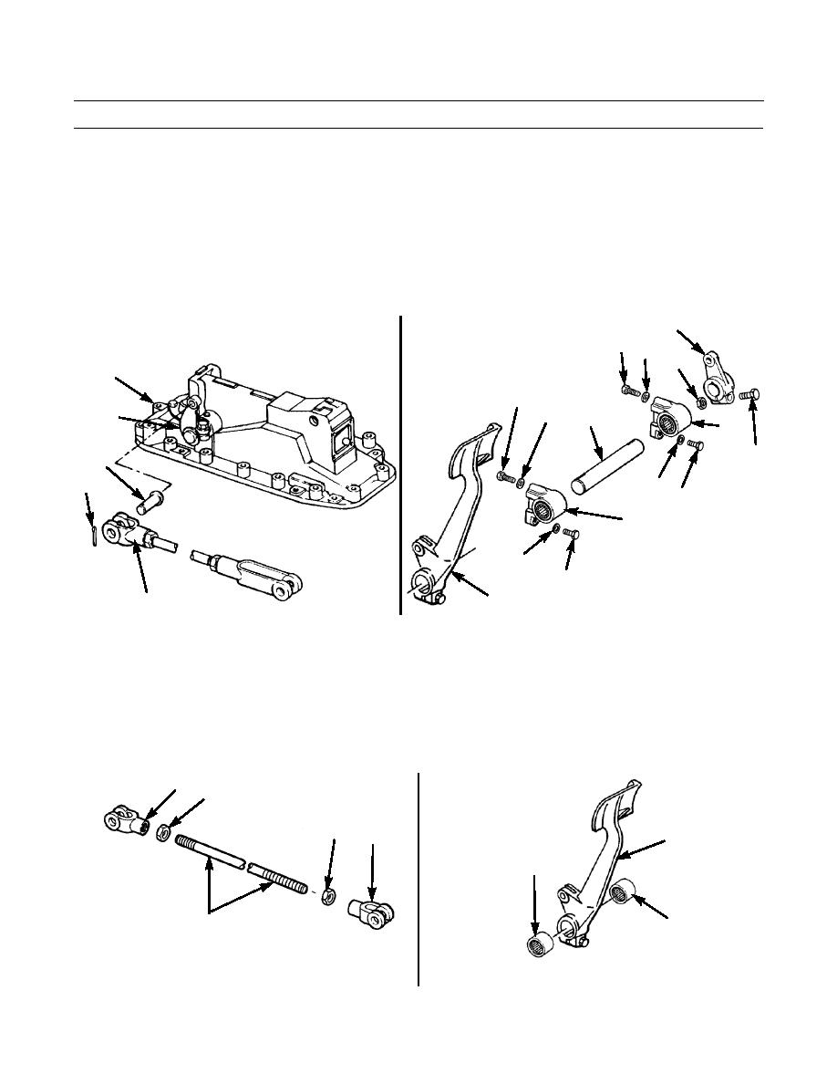
REMOVAL - CONTINUED
9.
Remove cotter pin (15) and pin (16) from rod end (17). Discard cotter pin.
10.
Remove rod end (17) from lever (18) on brake actuating mechanism (19).
11.
Remove nut (20) and bolts (21) from lever (22).
12.
Remove four bolts (23) and lockwashers (24) from both bellcranks (25). Discard lockwashers.
13.
Remove shaft (26), L. H. foot pedal (27), bellcranks (25) and lever (22) as an assembly from crossbeam under floor.
14.
Remove lever (22) from end of shaft (26).
15.
Slide shaft (26) out of both bellcranks (25) and L.H. pedal (27).
22
23 24
R.H. BRAKE
20
ACTUATOR
19
23
24
18
26
25
21
16
15
24
23
25
24
23
27
17
386-643
386-421
DISASSEMBLY
NOTE
Only one rod, brake pedal and bellcrank are shown. Procedures for disassembly are the same for all others.
1.
Loosen nut (28) from each end of rod (29). Remove nuts and two rod ends (7).
2.
Remove two bearings (30) from foot pedal (4).
7
28
28
7
4
30
30
29
386-423
386-424
0121 00-3
|
|
Privacy Statement - Press Release - Copyright Information. - Contact Us |
