 |
|||
|
|
|||
|
|
|||
| ||||||||||
|
|
 TM 5-2410-233-23
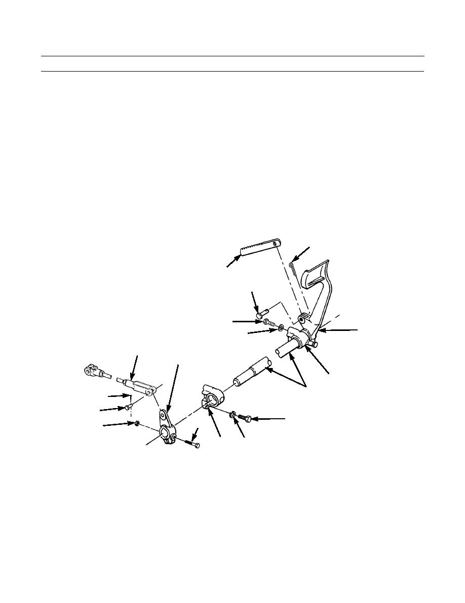
STEERING BRAKE PEDALS AND LINKAGE MAINTENANCE - CONTINUED
0121 00
REMOVAL
NOTE
This procedure is to be used for R.H. or L.H. brake pedal and linkages.
1.
Remove cotter pin (1), pin (2) and ratchet (3) from R.H foot pedal (4). Discard cotter pin.
2.
Repeat step 2 for ratchet (3) on L.H foot pedal.
3.
Remove cotter pin (5), pin (6) and disconnect R.H. rod end (7) from lever (8). Discard cotter pin.
4.
Repeat step 3 for L. H. side to remove rod end (7).
5.
Remove four bolts (9) and lockwashers (10) from two bellcranks (11). Discard lockwashers.
6.
Remove shaft (12), R. H. foot pedal (4), bellcranks (11) and lever (8) as an assembly from machine.
7.
Remove nut (13), bolt (14) and lever (8) from shaft (12).
8.
Slide shaft (12) out of both bellcranks (11) and R.H. pedal (4).
1
3
2
9
4
10
7
8
11
12
5
6
R.H. PEDAL AND
9
14
13
LINKAGE ASSEMBLY
11
10
386-630
0121 00-2
|
|
Privacy Statement - Press Release - Copyright Information. - Contact Us |
